Teton SmartSlice 2.0 offers improved functionalities
Simulation tool for 3D printing provides more ergonomic user features, including view displacement options, tooltips and 10 new material options.

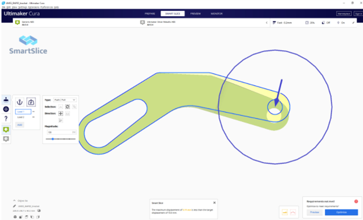
SmartSlice view displacement tool. All photo Credit: Teton Simulation Software
Teton Simulation Software (Layramie, Wyo., U.S.) has released version 20.2 of its SmartSlice software (see “Teton launches Smart Slice simulation 3D printing tool”), a simulation tool for optimizing 3D printer performance. New functionalities for this version include view displacements, tooltips, 10 new materials and the ability to sort optimized results by cost and identify regions of the part that may require modification.
Via the “view displacement” feature, users are now able to view how a part deflects under the prescribed Use Case, ensuring a problem is set up correctly.
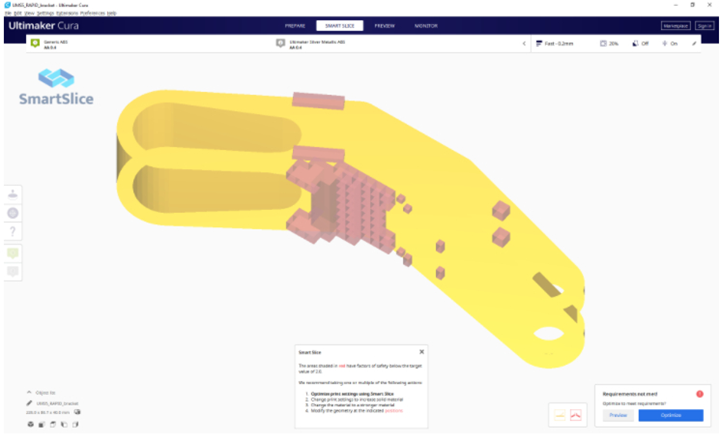
Teton has also implemented the ability to inform users after a Validation, or after an unsuccessful Optimization as to next steps if the as-printed geometry with the specified material and slice settings does not meet stiffness or strength requirements, including:
- Optimizing slice parameters using SmartSlice to meet the requirements
- Manually modifying the slice parameters to meet the requirements
- Changing the material to a stronger (or) stiffer material
- Highlighting regions of the geometry which could be modified to meet requirements.
For the last option, SmartSlice will now show the user where the part is either (a) the weakest, or (b) the softest. The user can then take appropriate action to ensure their part will perform as expected.
Similarly, if SmartSlice cannot find a set of slicing parameters to meet the desired requirements, the user will be shown the areas of the geometry which need modification, and suggest the user either:
- Change the material to a stronger (or) stiffer material
- Modify the geometry at the indicated regions to meet the requirements.
An additional feature, tooltips, are now available on all buttons within SmartSlice to inform users what the buttons do, and are available for
all optimized results, enabling users to understand which slice parameters are being modified for the optimized result. Further, links to help and tutorials are now embedded directly within the toolbar on the left of the screen.

Users are now informed when an as-printed component does not meet requirements.
With Teton’s Cura feature, users are able to enter costs for materials to price prints from a material perspective. The ability to sort and filter optimization results by print time, mass, factor of safety, maximum displacement and cost are possible.
Last, with the goal to continually add to its materials database from a variety of material suppliers, Teton has built on Fiberthree PA-CF Pro, Fiberthree PA-GF Pro, igus GmbH iglidur I150, igus GmbH iglidur I180, Jabil PA 4535 CF, Jabil PETg 0800 ESD, MatterHackers NylonG, MatterHackers NylonX, Polymaker PolyMide PA6-CF and Polymaker PolyMide PA6-GF. Currently the software holds 40 different material options.
Related Content
-
3D-printed CFRP tools for serial production of composite landing flaps
GKN Aerospace Munich and CEAD develop printed tooling with short and continuous fiber that reduces cost and increases sustainability for composites production.
-
Plant tour: Spirit AeroSystems, Belfast, Northern Ireland, U.K.
Purpose-built facility employs resin transfer infusion (RTI) and assembly technology to manufacture today’s composite A220 wings, and prepares for future new programs and production ramp-ups.
-
Large-format 3D printing enables toolless, rapid production for AUVs
Dive Technologies started by 3D printing prototypes of its composite autonomous underwater vehicles, but AM became the solution for customizable, toolless production.


.jpg;maxWidth=300;quality=90)


