Bending of composite material compression specimens
Dr. Donald F. Adams, president of Wyoming Test Fixtures (Salt Lake City, Utah) looks at the effect bending has on compression testing of composite specimens.
In my previous column, I discussed the influence of column buckling of the composite material test specimen on its measured compressive strength (see "Buckling of composite material compression specimens," under Editor's Picks," at top right). As an aside, it was noted that column bending is often present simultaneously, suggesting a potential interaction of these two effects that could further reduce the measured compressive strength. The discussion was supported by two graphs: an experimental plot of specimen compressive stress vs. strain indicating column buckling in the absence of column bending, and a corresponding plot of a specimen that exhibited bending but no column buckling.
It was shown that column buckling can cause a drastic reduction in the apparent compressive strength of the material. It was further indicated that the compressive strength of the same material, even in the presence of bending, was much higher when buckling did not occur. How much the strength might have been degraded by bending was not addressed. Therefore, I promised to discuss that question this time.
My short answer is, there is minimal influence on the measured compressive strength even when the percent bending induced in the specimen during testing is very high. But because this isn’t a generally accepted statement in the composites community, much more must be said.
To begin, ASTM D 3410, “Compressive Properties of Polymer Matrix Composite Materials with Unsupported Gage Section By Shear Loading,” states that the percent bending, defined as the quantity By = [(ε1-ε2)/(ε1+ε2)] x 100, where ε1 is the strain measured by a gage on one surface of the specimen and ε2 is the strain measured by a gage on the opposite surface, shall be less than 10 percent for all five of the specimens that are required to have back-to-back strain gages. Issued some years later, ASTM D 6641, “Compressive Properties of Polymer Matrix Composite Materials Using a Combined Loading Compression (CLC) Test Fixture” copied that requirement.
A variety of studies, however, have indicated that limiting bending to 10 percent for all specimens is no trivial matter. This is the case, in part, because the causes of bending in a compression test can be separated into at least three groups:
1) Errors in testing machine alignment. Because the various compression test fixtures are typically loaded between flat platens, a lack of parallelism between these platen-loading surfaces is a potential source of induced bending in the specimen. The ASTM standards suggest using either well-aligned fixed platens, or one fixed platen and one spherical-seat platen. It has been shown that equivalent results can be obtained with either approach.1 If two fixed platens are used, parallelism within 0.0127 mm/0.0005 inch across 150-mm/6-inch diameter platens can be achieved using a dial indicator. Two fixed platens are often used because they ensure that platen alignment accuracy will be maintained from one test to the next.
2) Errors in test fixture alignment. As is true for the platens, the contacting surfaces of the fixture must also be flat and parallel. Beyond fixture fabrication errors, deformations and other damage that occurs during repeated use of the fixture also can induce specimen bending.
3) Errors in specimen fabrication. Perhaps most importantly, poor specimen preparation practices can result in major problems. Specimen thickness must be uniform. Local high spots, or even a taper of the specimen over its length or width, can lead to nonuniform loading and, thus, induced bending. And if specimen tabs are used, poor specimen quality can be compounded by tabbing material nonuniformities and/or nonuniform adhesive layer thicknesses.
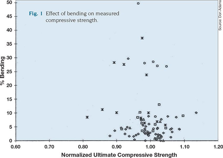
The influence of induced test specimen bending on measured compressive strength is indicated in Fig. 1 (p. 15). Each symbol represents an individual compression test of some type of carbon/epoxy cross-ply laminate. Tests were performed per either ASTM D 3410 or ASTM D 6641.1 As will be noted, although there is some scatter in the compression strengths, there is no trend toward decreased strength as percent bending increases. Because most of these tests were conducted according to the guidelines outlined above for obtaining good test results, most of the bending values are 10 percent or less. However, even those tests that resulted in bending of 30 percent or more indicated no trend toward decreasing compressive strength. Incidentally, none of the specimens represented in Fig. 1 buckled, even when the bending was excessive.
One explanation for why bending is not particularly detrimental in the compressive test of a composite specimen is presented by Wegner and Adams1 and summarized here: Fiber microbuckling, that is, local buckling of individual fibers or small groups of fibers, is generally considered to be the primary cause of the eventual compressive failure of a fiber-reinforced composite. As a typical specimen is loaded in compression, a natural curvature develops in the specimen due (as noted above) to some misalignment of the load and/or some specimen fabrication irregularity. Thus, the fibers on the concave surface of the specimen curvature will tend to microbuckle first because they are the most highly stressed.
However, the presence of fibers in the plies adjacent to these stressed surface fibers restricts the extent to which the stressed fibers can buckle inward, and these stressed fibers do not naturally buckle outward because the curvature present in the specimen is in the opposite direction. For that reason, fibers in the outermost ply on the concave surface do not microbuckle immediately and they and the remainder of the composite continue to carry the increasing load. Although the fibers in the next ply eventually approach their microbuckling limit, the inwardly adjacent plies and the specimen curvature, as before, constrain these second-ply fibers from microbuckling. This process continues progressively until the lateral support offered by the remaining adjacent plies is too small to constrain microbuckling. When fibers finally microbuckle, the resulting instability causes the whole specimen to immediately collapse.
We know, intuitively, that it is good practice to minimize bending along with any other anomaly when we perform this type of testing. But given the above, the ASTM’s requirement that bending in a compression test be limited to 10 percent or less might be unnecessarily restrictive.
Reference:
1P.M. Wegner and D.F. Adams, “Verification of the Combined Load Compression (CLC) Test Method,” Final Report DOT/FAA/AR-00/26, Federal Aviation Admin. (Washington, D.C.), August 2000.
Related Content
Composite sidewall cover expands options for fire-safe rail components
R&D project by CG Rail explores use of carbon fiber-reinforced thermoplastics and recycled manufacturing scrap to meet fire safety, weight and volume targets.
Read MoreImproving carbon fiber SMC simulation for aerospace parts
Simutence and Engenuity demonstrate a virtual process chain enabling evaluation of process-induced fiber orientations for improved structural simulation and failure load prediction of a composite wing rib.
Read MoreJeep all-composite roof receivers achieve steel performance at low mass
Ultrashort carbon fiber/PPA replaces steel on rooftop brackets to hold Jeep soft tops, hardtops.
Read MoreThe basics of composite drawing interpretation
Knowing the fundamentals for reading drawings — including master ply tables, ply definition diagrams and more — lays a foundation for proper composite design evaluation.
Read MoreRead Next
Buckling of composite material compression specimens
Dr. Donald F. Adams (Wyoming Test Fixtures, Salt Lake City, Utah) rehearses the causes of, and solutions for, problems with buckling in composite compression specimens.
Read MoreAll-recycled, needle-punched nonwoven CFRP slashes carbon footprint of Formula 2 seat
Dallara and Tenowo collaborate to produce a race-ready Formula 2 seat using recycled carbon fiber, reducing CO2 emissions by 97.5% compared to virgin materials.
Read MoreVIDEO: High-volume processing for fiberglass components
Cannon Ergos, a company specializing in high-ton presses and equipment for composites fabrication and plastics processing, displayed automotive and industrial components at CAMX 2024.
Read More


