Photo Credit: ambliFibre project, Fraunhofer IPT
Thermoplastic composites (TPCs) have been promoted extensively in recent years due to their high potential to increase production rates and enable weight reduction. One of the most discussed topics for increasing production rates with TPCs is in-situ consolidation (ISC) during automated fiber and tape placement (AFP/ATP).
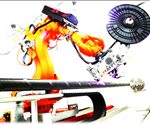
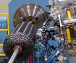
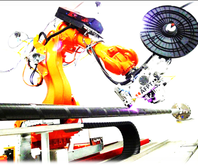
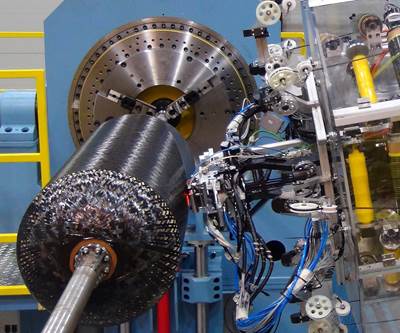
ISC was actually first demonstrated with constrained structures such as tubes, and continues to offer great potential for overwrapped pressure vessels and storage tanks. These structures can be produced using laser-assisted tape winding (LATW), which comprises a laser-assisted tape placement (LATP) machine and a rotating mandrel (Fig. 1).
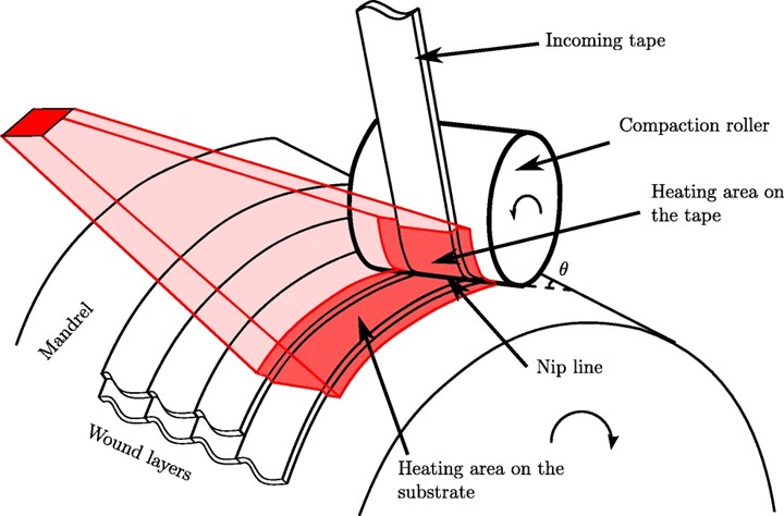
Fig. 1. LATW process. Photo Credit: Fig. 1, Hosseini, Baran, van Drongelen and Akkerman. “On the temperature evolution during continuous laser-assisted tape winding of multiple C/PEEK layers: The effect of roller deformation.” Int J Mater Form (June 2020).
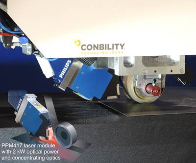
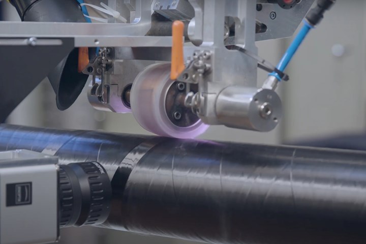
The AFP/ATP head is installed on a CNC six-axis robot and uses a laser to heat the incoming tape and substrate to melt the thermoplastic polymer. The tape is then pressed onto the substrate using a roller to promote interlayer adhesion and consolidation.
First-ply strategies
Like any additive manufacturing process, the first ply in LATW is an issue that should be addressed. For a tube produced on a metal mandrel (aluminum is preferred), mandrel extraction post-winding should be considered and a release agent applied.
Another consideration is fixation. If hoop winding is applied to the first ply (versus a helical or axial layup, Fig. 2), adhesive tape can be manually placed at the beginning and the end of the course to improve stability and adhesion to the incoming tape. If a helical or axial layup is required, then complete tape rings should be applied and fixed at the edges of the cylinder, using adhesive tape to prevent slippage.

Fig. 2 Hoop winding is at roughly 90° to the mandrel axis, polar winding is at an angle much closer to 0° (or the axial direction) and helical winding is at an angle in between. Photo Credit: CW.
For a Type IV pressure vessel (plastic liner with carbon fiber composite overwrap), or when overwrapping a plastic pipe, the incoming tape will be fused to the liner. This eliminates the need for adhesive tape fixation, but the plastic liner and TPC tape should have the same base polymer to ensure proper bonding.
Issues may arise with heating the plastic liner. For example, if it cannot absorb the laser heating, or if a metal mandrel is used, consider adjusting the laser angle to fully heat the incoming tape. In other words, instead of the typical positioning so that the laser is distributed between the incoming tape and the substrate (Fig. 1), angle the laser more toward the tape. This will avoid laser reflections, ensure more uniform heating of the tape and reduce energy consumption.
Laser distribution changes with ply angle or changing geometry
As described above, typically during LATP and LATW processes, the laser is distributed between the incoming tape and the substrate. This distribution is constant in cases where the radius geometry and layup direction are constant. However, there are considerations. For example, during an axial layup on a tubular mandrel (which would be roughly equivalent to the flat mold in Fig. 3), the incoming tape will receive the same radiation compared to a hoop layup while the substrate will receive more laser projection than in a hoop layup. Note, this is negligible in large-diameter tubes.
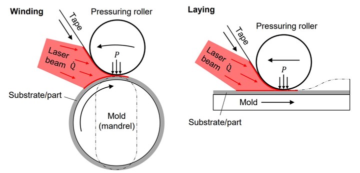
Fig. 3 Laser-assisted placement processes: tape winding (left) and tape laying (right). Photo Credit: Fig. 1.5, “Thermal Skin Effect in Laser-Assisted Tape Placement of Thermoplastic Composites” by Thomas Weiler, Jan. 2020.
During heating, the thermoplastic tape spreads and becomes wider and thinner, depending on the temperature and layup speed (heating time), due to reduced polymer viscosity. In a system with closed-loop control — where temperature is kept constant on the heating area — an axial layup will end up with a wider tape than in a hoop layup. Alternatively, in a system with constant power control, the axial layup will develop under lower temperatures, and thus the tape will widen less. This is important to understand and address because uneven changes in tape dimensions can result and cause undesired gaps and overlaps that might increase void content.
When wrapping tubes, the radius geometry is constant, but this changes when wrapping pressure vessels due to the end domes. While entering or exiting these domes, the robot slows down and the size of the laser spot decreases on the substrate. Both actions can cause a sharp increase in temperature, which may cause thinner sections, different material properties or even damage to the polymer.
Another consideration is that as the part’s fiber layers are built up during winding, the dimensions of the core being wound onto (mandrel plus plies so far) are changing. Thus, layup angles should be adjusted to avoid gaps. An LATP/LATW system with software that updates the mandrel diameter might be available from some suppliers. If not, the winding will have to be inspected manually or with an inline inspection system and corrected as necessary.
Although addressing the above considerations helps, it isn’t possible to achieve 100% elimination of defects such as gaps, overlaps and thickness variations. The winding process, therefore, should be developed to achieve the part’s design allowables rather than pursuing a “perfect part,” which may add unnecessary cost.
Maximizing mechanical properties, interlayer adhesion and crystallinity
Thermal management is a key factor to achieve adequate interlayer adhesion as well as full potential crystallinity in the thermoplastic matrix. First layers are close to the mandrel, which acts as a heat sink. This may prevent molecular interdiffusion and promote poor interlayer adhesion, low crystallinity and higher void content. To overcome this challenge, one should consider reducing layup speed, increasing temperature and adjusting laser angle to enable a longer heating time to ensure molecular diffusion.
This does not ensure, however, full crystallinity. This is because molecular diffusion — reforming molecular re-entanglements after melt during cooling — is a much faster process than crystallization, where molecules are aligned to form an ordered crystalline structure. If the part being made is thin (roughly less than 2 millimeters), one would expect lower crystallinity than for a thicker part, which receives more consolidation passes and less heat loss to the mandrel. For both thin and thick parts, consider slower layup speeds for initial plies.
To reach full crystallinity, consider the following:
- After winding, anneal (heat soak) at a temperature between the thermoplastic matrix Tg (glass transition temperature) and Tm (melt temperature). As a rule of thumb, the middle between the two temperatures provides the fastest crystallization kinetics.
- Use a heated mandrel that will promote crystallinity of initial layers. This is not always possible and it may be more expensive. If a heated mandrel is used, be sure to consider that the mandrel might undergo thermal expansion.
- Program passes for consolidation — in other words, include winding passes without incoming tape but with laser fully projected on the substrate. This is mostly done on latter plies that receive fewer passes but can also be done on first plies to improve interlayer adhesion.
Tape dimensions – design flexibility and production rates
Tape dimensions are a crucial parameter in tape winding. Obviously, receiving constant tape width and thickness from the supplier will enable repeatable and uniform products. However, tape dimensions also define design flexibility. For example, with an axial layup on a tubular mandrel, the tape width should be narrow enough to be compliant with the mandrel curvature. The larger the mandrel diameter, the wider the tape that can be used. Wider tape means faster throughput while narrower tape is more design-friendly since it is more compliant to curvature changes and easier to steer.
Although there are more issues and challenges with LATW, good parts are possible, and this method of manufacturing will continue to advance as composite tubes and tanks are used for hydrogen and other gas storage applications.
About the Author
Yehiel Shaham
Yehiel Shaham is a plastics and polymers engineer with nearly 12 years of experience in development and manufacturing of thermoplastics from leading Israeli plastics and defense companies. During 2016-2020, he was the thermoplastic composites (TPCs) lead engineer in RAFAEL, where he specialized in TP-AFP. Currently, he is aiming to promote TPCs in Israeli industry.
Related Content
MFFD thermoplastic floor beams — OOA consolidation for next-gen TPC aerostructures
GKN Fokker and Mikrosam develop AFP for the Multifunctional Fuselage Demonstrator’s floor beams and OOA consolidation of 6-meter spars for TPC rudders, elevators and tails.
Read MorePlant tour: Airbus, Illescas, Spain
Airbus’ Illescas facility, featuring highly automated composites processes for the A350 lower wing cover and one-piece Section 19 fuselage barrels, works toward production ramp-ups and next-generation aircraft.
Read MoreDeveloping repairs for thermoplastic composite aerostructures
HyPatchRepair project proves feasibility of automated process chain for welded thermoplastic composite patch repairs.
Read MorePEEK vs. PEKK vs. PAEK and continuous compression molding
Suppliers of thermoplastics and carbon fiber chime in regarding PEEK vs. PEKK, and now PAEK, as well as in-situ consolidation — the supply chain for thermoplastic tape composites continues to evolve.
Read MoreRead Next
INOMETA invests in new laser-assisted tape winding technology
Using the new automated manufacturing process, the company aims to expand its current thermoplastics product range with an eye toward mass production.
Read MoreFraunhofer and Conbility join forces to commercialize tape layer
Two AZL Aachen GmbH partners have joined forces for commercialization of a tape-placement and tape winding system.
Read MoreMikrosam launches hybrid AFP & FW solution for composites production
The hybrid work cell integrates the advantages of filament winding (FW) and automated fiber placement (AFP) technologies.
Read More

