Comparison of shear-loaded compression test fixtures
Dr. Donald F. Adams compares the three basic types of shear-loaded compression test fixtures.
I noted in a 2005 column (see "Current compression test methods" under “Editor's Pick,” at top right) that there are three basic methods of loading a composite material test specimen in compression: end loading, shear loading and combined loading. At that time, combined loading had been ASTM Standard D6641 for only four years.1 Nevertheless, I suggested that combined loading eventually would be the sole survivor, but the process would be evolutionary rather than revolutionary, and the other compression test methods and their various modifications would be around for many years to come. That statement remains valid. While acceptance of the combined loading compression test method has grown steadily — it is now the dominant one — use of the other two has risen and then subsided several times since that time. The shear-loaded compression test methods are presently enjoying a resurgence.
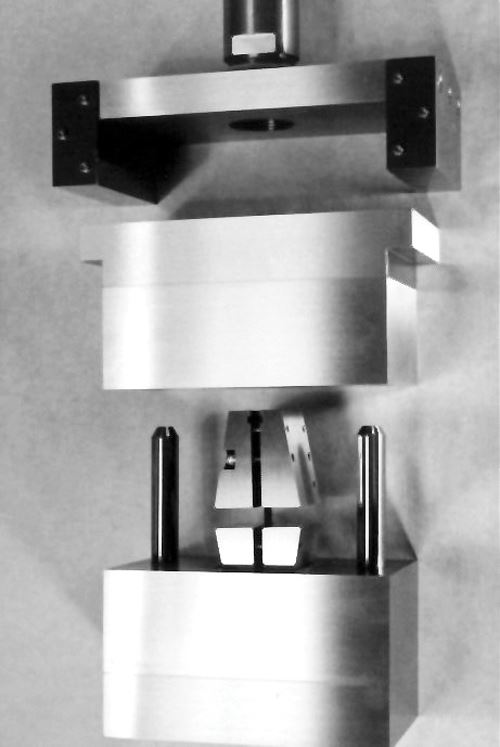
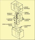
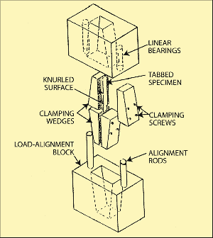
There is one ASTM standard for shear-loaded compression, ASTM D3410, and it includes only one test fixture geometry.2 Although it is not specifically identified in the standard, this is commonly referred to as the IITRI (Illinois Institute of Technology Research Institute) design, a typical version of which is shown in Fig. 1. There are other versions as well, but they are similar in concept to the one shown here. Its key features include the use of flat wedge grips and alignment rods in ball bearings. Tabbed specimens up to 38 mm/1.50 inches wide and 15 mm/0.60 inch thick in the tabbed region can be accommodated. This large capacity, combined with the relatively inefficient design of the base blocks, results in a very large and heavy fixture, which is correspondingly expensive to fabricate. The typical fixture shown in Fig. 1 weighs approximately 43 kg/95 lb.
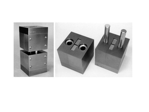
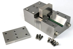
The IITRI fixture encouraged the design of smaller versions that incorporate the same basic features. An example is shown, both assembled and disassembled, in Fig. 2. This fixture weighs only 10 kg/23 lb, but it is limited to a maximum specimen width of 13 mm/0.50 inch. However, it should be noted that most composite compression specimens are only 13 mm/0.50 inch wide anyway, which is why this fixture was designed for this width.
Another example, the so-called Celanese compression test fixture, for which ASTM D3410 was originally written in 1975, used a specimen only 0.64 mm/0.25 inch wide. The testing community eventually considered this a bit too narrow. The Celanese fixture used a cone-in-cone design to apply the shear loading. That is, each end of the tabbed specimen was clamped between the two halves of a split cone, which was then placed in a mating cone to which an axial compressive force was applied. This configuration, consisting of a specimen mounted between cones, was held in axial alignment by a thin sleeve slipped over the complete assembly. There were fundamental criticisms of the Celanese design: (1) it was difficult to continually maintain the required circular cross-sectional shape of the split cones as the tabbed specimen was being squeezed by the grips; and (2) there was the potential for friction between the cones and the sleeve. As a result of these factors, the IITRI fixture was added to ASTM D3410 in 1987 as an alternate method, and in 2003 the Celanese fixture was deleted from the standard.
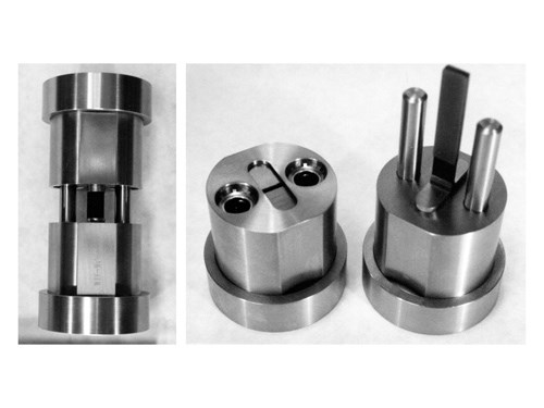
However, the original Celanese fixture did prompt the development of at least two modified versions. The so-called Wyoming-Modified Celanese compression fixture is shown, both assembled and disassembled, in Fig. 3. It will accommodate a specimen up to 13 mm/0.50 inch wide. The alignment sleeve is replaced with alignment rods and bearings like those used with the IITRI fixture. Tapered cylinders, rather than tapered cones, form the specimen grips. Because they have a constant radius along their length, the tapered cylinders maintain full contact with their mating base blocks, independent of their axial position, and thus can accommodate variations in tabbed specimen thickness. Moreover, the flat wedges of the IITRI fixture distribute force in a single diametrical direction, which can deform the fixture, but the tapered cylinders tend to distribute the force into the base blocks in a radial manner (that is, in all possible diametrical directions), preserving the fixture shape. Tapered cylinders also permit the use of circular base blocks, as shown in Fig. 3, rather than the rectangular base blocks shown in Figs. 1 and 2, with a corresponding reduction in fixture weight. Specifically, the Celanese and Wyoming-Modified Celanese fixtures each weigh only about 4.5 kg/10 lb.
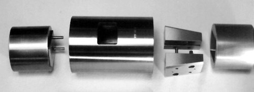
Another modification, combining the flat grips of the IITRI fixture but retaining the circular shape and alignment sleeve of the Celanese fixture, was standardized by DIN in 1991.3 This fixture is shown disassembled in Fig. 4. However, this so-called German-Modified Celanese fixture has not achieved significant attention because the Wyoming-Modified Celanese fixture incorporates a much more logical combination of features.
In summary, there are three fixture types for shear loaded compression testing. For specimens 13 mm/0.50 inch wide or narrower, the Wyoming-Modified Celanese fixture is much less expensive and more easily handled than the other types. Because it is less massive than the IITRI fixture, it can be heated and cooled more quickly during nonambient temperature testing. However, this advantage is somewhat mitigated by the fact that when the IITRI fixture is at temperature, only the grips have to be removed from the temperature chamber to change specimens.
If specimens wider than 13 mm/0.5 inch are to be tested, the standard IITRI fixture is the logical choice. It performs well and is widely available. The Wyoming-Modified Celanese type of compression fixture could be scaled up to accommodate larger specimens, potentially resulting in a significant fixture weight and cost reduction compared to the standard IITRI fixture, but I have no knowledge, to date, of anyone having done so.
References
1ASTM D6641/D6641M-09, “Standard Test Method for Compressive Properties of Polymer Matrix Composite Materials Using a Combined Loading Compression (CLC) Test Fixture,” ASTM International (W. Conshohocken, Pa.), 2009.
2ASTM D3410/D3410M-03(2008), “Standard Test Method for Compressive Properties of Polymer Matrix Composite Materials with Unsupported Gage Section by Shear Loading,” ASTM International (W. Conshohocken, Pa.), reapproved 2008.
3DIN Standard 65 380, “Compression Test of Fiber Reinforced Aerospace Plastics: Testing of Unidirectional Laminates and Woven-Fabric Laminates,” Deutsches Institut für Normung (Köln, Germany), 1991.
Related Content
Crashworthiness testing of composites: A building block approach, Part 2
Following the previously discussed coupon-level testing element, subcomponent and component testing are the next steps in designing crashworthy composite structures.
Read MoreComposite test methods (and specifications) for fiber-reinforced concrete structures
While initially focused on transitioning existing standards published by the American Concrete Institute, the relatively new ASTM Subcommittee D30.10 is developing new standardized test methods and material specifications for FRP composites.
Read MoreDamage tolerance testing of sandwich composites: The sandwich CAI test
A new ASTM-standardized test method established in 2022 assesses the compression-loaded damage tolerance of sandwich composites.
Read MoreNumerical tool with mean stress correction demonstrated for fatigue life estimation of thermoplastic composites
To aid design of fatigue-resistant structures, Econ Engineering has developed an algorithm to evaluate ply-based cyclic stiffness degradation combined with an FE failure check, validated for a CF/PAEK pressure vessel.
Read MoreRead Next
Current compression test methods
Dr. Don Adams discusses the test methods and fixtures currently available to test the compressive strength of composites.
Read More“Structured air” TPS safeguards composite structures
Powered by an 85% air/15% pure polyimide aerogel, Blueshift’s novel material system protects structures during transient thermal events from -200°C to beyond 2400°C for rockets, battery boxes and more.
Read MorePlant tour: Daher Shap’in TechCenter and composites production plant, Saint-Aignan-de-Grandlieu, France
Co-located R&D and production advance OOA thermosets, thermoplastics, welding, recycling and digital technologies for faster processing and certification of lighter, more sustainable composites.
Read More
