Damage tolerance testing of sandwich composites: The sandwich CAI test
A new ASTM-standardized test method established in 2022 assesses the compression-loaded damage tolerance of sandwich composites.
Damage tolerance testing of composites refers to the testing of specimens with a centrally located damage site, under a specified loading condition. Typically, the damage is produced by drop-weight impacting, which can cause extensive internal damage that is difficult to detect by visual inspection. For composite laminates, damage tolerance testing is typically performed under in-plane compression loading because their compression strengths are lower than their tension strengths and, therefore, more critical in many designs. Additionally, impact damage typically has a greater effect on the compression strength. The ASTM D71371 test method, initially standardized in 1999, is commonly followed for determining the compression-after-impact (CAI) strength of composite laminates. Until recently, however, considerably less emphasis has been placed on developing standardized damage tolerance test methods for sandwich composites.
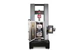
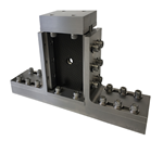
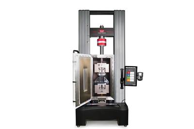
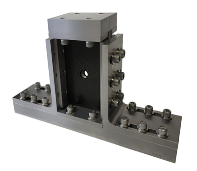
In 2011, ASTM International (West Conshohocken, Pa., U.S.) published a standardized practice for damage resistance testing of sandwich composites, ASTM D77662, which provides supplemental instructions for imparting damage to sandwich composite specimens following either ASTM D62643 for quasi-static indentation (Procedures A and B) or ASTM D71364 for drop-weight impact testing (Procedure C). In 2022, two new sandwich damage tolerance test methods were standardized: a sandwich CAI test and a sandwich flexure-after-impact (FAI) test. In this column, we’ll focus on the new compression-loaded damage tolerance test method for sandwich composites, ASTM D82875, shown in Fig. 1.
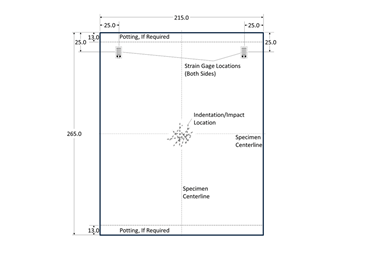
Based on previous research investigations6-9 and a series of experimental evaluations10 performed during test method development, a standard sandwich CAI specimen size of 215 millimeters in width and 265 millimeters in length was established. These specimen dimensions were increased in relation to the 100-millimeter-wide and 150-millimeter-long laminate CAI specimen to allow for the larger damage areas produced in sandwich composites and to accommodate the use of strain gages for specimen alignment. Although quasi-isotropic laminates are typically used for laminate CAI testing, the facesheet ply layup and core configuration for sandwich composite CAI specimens are often selected to represent the intended structural application. In some cases, however, the core thickness must be increased to avoid specimen buckling under compression loading. Additionally, potting of the core region at the specimen ends may be required to avoid facesheet separation or end-brooming prior to specimen failure.
Similar to the ASTM D7137 test method for damage tolerance testing of composite laminates, ASTM D8287 requires that the loaded ends of the sandwich specimen are machined parallel within tight tolerances. Four bonded strain gages, mounted onto the facesheets in the loading direction, are used for specimen alignment prior to testing. Based on the results of finite element analyses10, the preferred strain gage placements are 25 millimeters from the specimen outer edges and either 25 millimeters below the top edge of the specimen or 12 millimeters below the upper potted region, whichever is greater. The standard specimen dimensions and strain gage locations are shown in Fig. 2.
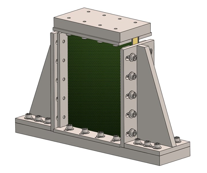
The test fixture used for sandwich CAI testing (Fig. 1) is a scaled-up version of the ASTM D7137 laminate CAI test fixture that can accommodate sandwich specimen thicknesses up to 50 millimeters. The end-loading fixture consists of a base, two vertical supports and a top plate. The base and top plate use adjustable, flat-faced specimen supports that provide some restraint to out-of-plane rotation and prevent end-brooming of the facesheets. The vertical supports use adjustable knife-edged specimen side supports that provide out-of-plane restraint to buckling. The height of the vertical supports is reduced to produce a small gap adjacent to the top plate to allow for the reduction in specimen length during compression loading.
After the sandwich specimen is secured into the test fixture, the assembly is placed between the platens of the testing machine and aligned with the loading axis. A locking spherical-seat platen is recommended, but not required, for specimen alignment using the four bonded strain gages. If a spherical-seat platen is not used, shims placed between the fixture and platens may be incorporated for alignment. To align the specimen, the assembly is compression loaded to approximately 10% of the estimated maximum force and the four strain gage readings are obtained. Differences in strain between the gages indicates specimen bending or uneven load introduction. If the difference in the readings exceeds 10%, the specimen is unloaded and the spherical-seat platen locking screws are adjusted. If a spherical platen is not used, shims are inserted between the platens and test fixture. This alignment procedure is repeated until all four strain gage readings are within 10%. The sandwich specimen is then compression loaded at a constant displacement rate and the applied force, crosshead displacement and strain data from the bonded strain gages are recorded. Once the peak force is reached and the measured force drops by more than 30% from the peak value, the loading is halted to help identify the initial failure mode and location for later evaluation. The sandwich CAI strength is calculated using the peak applied force, and the total cross-sectional area of the two facesheets.
Minor end crushing before final failure in the gage section sometimes occurs, but if a valid gage section failure is ultimately achieved, such end crushing does not necessarily invalidate the test — what does invalidate it, however, is the onset of specimen instability or excessive bending. Gage section failures away from the impact damage are considered acceptable, and may indicate that the specimen is not sensitive to the induced damage, such that it fails at a compressive stress near the specimen’s undamaged strength. While this test method may also be used to test undamaged sandwich specimens for use in experimentally determining strength reductions due to impact damage, care should be taken to prevent undesirable failure modes such as end crushing. Note that the ASTM C36411 sandwich edgewise compression test, originally standardized in 1955, remains the recommended test methods for determining the undamaged sandwich compression strength.
References
1 ASTM D7137/D7137M-17, “Compressive Residual Strength Properties of Damaged Polymer Matrix Composite Laminates,” ASTM International (W. Conshohocken, PA, US), 2017 (first issued in 2005).
2 ASTM D7766/D7766M-23, “Damage Resistance Testing of Sandwich Constructions,” ASTM International (W. Conshohocken, PA, US), 2023 (first issued in 2011).
3 ASTM D6264/D6264M-23, “Measuring the Damage Resistance of a Fiber-Reinforced Polymer-Matrix Composite to a Concentrated Quasi-Static Indentation Force,” ASTM International (W. Conshohocken, PA, US), 2023 (first issued in 1998).
4 ASTM 7136/D7136M-20 “Measuring the Damage Resistance of a Fiber-Reinforced Polymer Matrix Composite to a Drop-Weight Impact Event,” ASTM International (W. Conshohocken, PA, US), 2020 (first issued in 2005).
5 ASTM D8287/D8287M-22, “Compressive Residual Strength Properties of Damaged Sandwich Composite Panels,” ASTM International (W. Conshohocken, PA, US), 2022.
6 Tomblin, J.S., Raju, K.S., Liew, J., and Smith, B.L., 2001, “Impact Damage Characterization and Damage Tolerance of Composite Sandwich Airframe Structures,” Final Report, DOT/FAA/AR-00/44.
7 Tomblin, J.S., Raju, K.S., and Arosteguy, G., 2004, “Damage Resistance and Tolerance of Composite Sandwich Panels – Scaling Effects,” Final Report, DOT/FAA/AR-03/75.
8 Butterfield, J.M., and Adams, D.O., “Effects of Stitching on Compression After Impact Strength of Sandwich Composites,” Long Beach, CA: Proceeding of the 49th International SAMPE Symposium and Exhibition, 2004.
9 Butterfield, J.M., 2006, “Damage Tolerance of Stitched Carbon Composite Sandwich Structures,” M.S. Thesis, University of Utah.
10 Kuramoto, B., Stanfield, M., and Adams, D.O., “Development and Evaluation of the Sandwich Edgewise Compression After Impact Test,” to appear in the Journal of Sandwich Structures and Materials, 2024.
11 ASTM C364/C364M-16, “Edgewise Compressive Strength of Sandwich Constructions,” ASTM International (W. Conshohocken, PA, US), 2016 (first issued in 1955).
Related Content
Measuring ply-wise deformation during consolidation using embedded sensors
Strip-type shape sensor method claims real-time measurement of ply-wise deformation.
Read MoreInterlaminar tensile testing of composites: An update
New test method developments for measuring interlaminar tensile strength address difficulties associated with the ASTM D6415 curved beam flexure and ASTM D7291 flatwise tensile tests.
Read MoreMulti-scale 3D CT imaging enables digital twinning, high-fidelity simulation of composite structures
Computed tomography (CT) provides highly accurate 3D analysis of internal microstructure, performance simulation of carbon fiber/PEEK satellite strut.
Read MoreTesting to support composite bolted joint analysis
An overview of ASTM Standard Guide D8509, and its coupon-level mechanical testing of design properties for analyzing composite bolted joints.
Read MoreRead Next
Composite testing challenges, Part 1: Introduction to mechanical testing of composites
A range of standardized mechanical tests for complex composites are available and still under development for materials development, design and quality control requirements.
Read MoreDetermining the equivalency of composite test methods
While time consuming and somewhat subjective, the comparative assessment approach has been proven effective toward assessing composites test method equivalence.
Read MoreNotched testing of sandwich composites: The sandwich open-hole compression test
A new ASTM-standardized open-hole compression test method seeks to determine the notch sensitivity of sandwich composites.
Read More

