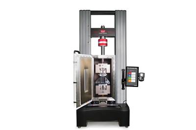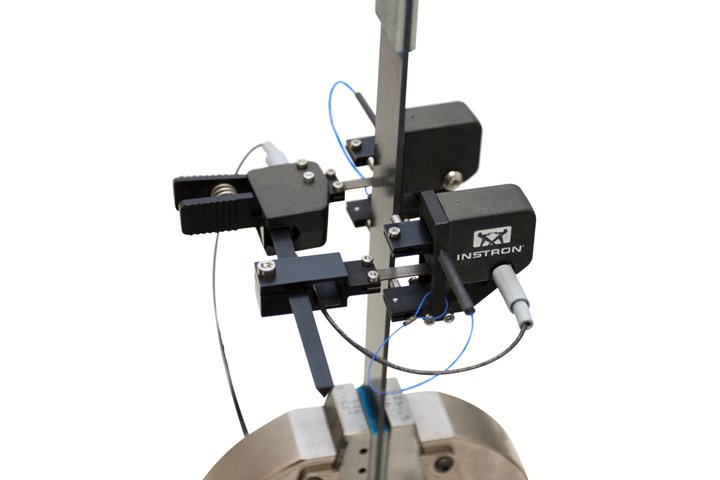
Figure 1. Biaxial clip-on extensometer. All photos: Instron
Compared to traditional structural materials, polymer matrix composites (PMC) offer greatly enhanced performance and flexibility. However, these benefits come at the cost of increased material complexity, and it is easy to overlook the challenges of producing high-quality test data to support the needs of materials development, design and quality control. In Part 2 of this three-part series on composites testing, we will discuss the various options for measuring strain when testing composites.
General aspects of strain measurements
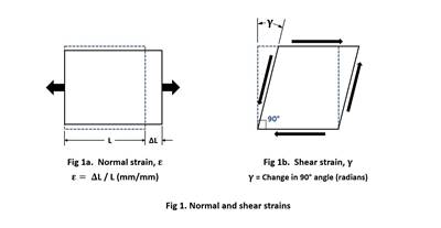
For tensile testing of composite materials, measurement of axial strain can be achieved using a single-strain measurement on one side of the test specimen. However, more consistent and accurate results can be achieved by taking a pair of measurements on opposite sides of the specimen and using their average to compensate for any misalignment. The use of an average strain measurement is essential for compression testing, as the difference between the two measurements is used to check for excessive specimen bending. Determination of Poisson’s ratio in tensile and compression testing requires the additional measurement of transverse strain.
Alternately, shear tests require the determination of shear strain, which can be calculated from measurements of axial and transverse strain. In V-notch shear tests, the strain distribution is non-uniform and concentrated between the notches in the specimen. Accurate measurement of these local strains requires the use of strain gauges.
Traditional approaches to strain measurement for composites testing use contacting methods including bonded strain gauges or clip-on extensometers. Recent developments in noncontacting strain measurement have enabled these same systems to offer similar performance to traditional contacting systems and provide significant additional benefits such as robustness and the ability to provide full-field strain maps.
Strain gauges
Strain gauges for composites testing usually consist of thin metal foil grids mounted on an insulating backing. Their operation relies on the change in resistance of an electrical conductor subject to an applied strain. The change in the resistance of a strain gauge at the strain levels encountered in composites testing (typically 3%) is small, and specialist strain gauge conditioning electronics are needed to provide accurate measurements.

Figure 2. Noncontact video extensometer mounted on a temperature cabinet.
The sensitivity of the gauge (known as the gauge factor) is required data for the calibration of the measurement system and is provided by the gauge manufacturer. To make accurate measurements, strain gauges must be correctly aligned and carefully bonded to the surface of test specimens (with specimens that have been wet conditioned, this can be difficult). Strain gauges are available in a variety of forms as either single gauge or as pre-aligned gauge combinations known generically as rosettes. Foil strain gauges can be used over a range of temperatures from cryogenic to more than 200⁰C.
Strain gauges are compact and can be used to measure strains over small regions such as in the notch of a V-notch shear test specimen or on either side of a short gauge-length compression specimen.
Strain gauges can provide very accurate strain measurements; however, they are a consumable item and are costly in terms of both their materials and the skilled labor needed to apply them.
Clip-on extensometers
Clip-on extensometers are widely used in the testing of composites. They are designed to attach to the test specimen and measure engineering strain by determining displacement over a fixed gauge length.
Several different types of clip-on extensometers are available. The most common type provides a single measurement of axial strain on one face of the test specimen. The averaging axial clip-on extensometer uses a pair of axial extensometers positioned on either side the specimen.
Measurement of shear strains and Poisson’s ratio requires the simultaneous measurement of axial and transverse strain. Transverse clip-on extensometers are similar in design to axial types, but they measure the change in width of the test specimen. Biaxial extensometers (Fig. 1), which integrate axial and transverse extensometers into a single unit, are more convenient to attach than two separate extensometers.
Most clip-on extensometers use strain-gauged flexures to measure displacement and can be used from cryogenic temperatures up to about 200°C. Clip-on extensometers using capacitive sensors are capable of operation above 200°C.
Automatic extensometers
Automatic extensometers are contacting types that can be remotely controlled. These extensometers can automatically engage and disengage from a test specimen and change gauge length. They are used for a wide range of high-volume tensile testing applications and are an essential part of automated (robotic) testing systems. Use of an automatic extensometer reduces the influence of the system operator and improves both throughput and the consistency of results.
Noncontact video extensometers
Noncontact video extensometers (Fig. 2) use high-resolution digital cameras and real-time image processing to determine strain by tracking the movement of contrasting marks on the test specimen.
As these extensometers do not make physical contact with the test specimen, there is no possibility of the extensometer influencing the material behavior or of the extensometer being damaged by the energy released when the test specimen fails. When testing inside a temperature chamber, the video extensometer can be located outside the chamber, isolating the measurement system from the hostile environment. As with automatic extensometers, noncontact video extensometers also reduce the influence of the operator, which improves the consistency of test results.
Full-field strain measurement
An exciting extension of the capabilities of video extensometers is the availability of integrated digital image correlation (DIC) software capable of producing full-field strain distributions (Fig. 3). This technique works by applying a random pattern to the surface of a test specimen, capturing a series of images during a test and then analyzing the images with an algorithm that determines first the displacement field and then the strain field for each image. The strain field information includes all the components of the strain tensor (i.e., axial, transverse, shear strain).
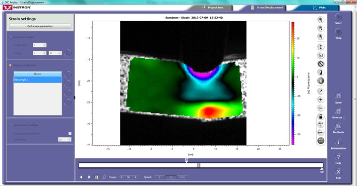
Figure 3. DIC analysis of bend test.
Compared to traditional methods, which measure a single component of local strain with a strain gauge, or use an extensometer to measure an average strain over a gauge length, full-field strain measurement yields an enormous amount of additional information that can help engineers and scientists better understand material behavior.
Next month, Part 3 of this three-part series will discuss the recommended system requirements that will help you test these materials accurately and efficiently.
Related Content
Multi-scale 3D CT imaging enables digital twinning, high-fidelity simulation of composite structures
Computed tomography (CT) provides highly accurate 3D analysis of internal microstructure, performance simulation of carbon fiber/PEEK satellite strut.
Read MoreDamage tolerance testing of sandwich composites: The sandwich CAI test
A new ASTM-standardized test method established in 2022 assesses the compression-loaded damage tolerance of sandwich composites.
Read MorePhotothermal tomography for locating, quantifying defects in composites
Years of infrared testing development result in thermography technology that is no longer just qualitative, but can define defect size and depth, making additional UT scans obsolete.
Read MoreNumerical tool with mean stress correction demonstrated for fatigue life estimation of thermoplastic composites
To aid design of fatigue-resistant structures, Econ Engineering has developed an algorithm to evaluate ply-based cyclic stiffness degradation combined with an FE failure check, validated for a CF/PAEK pressure vessel.
Read MoreRead Next
Composite testing challenges, Part 1: Introduction to mechanical testing of composites
A range of standardized mechanical tests for complex composites are available and still under development for materials development, design and quality control requirements.
Read MoreStrain measurement in composites testing
Columnist Dan Adams explores the most important considerations and most common methods for strain measurement.
Read MoreDeveloping bonded composite repair for ships, offshore units
Bureau Veritas and industry partners issue guidelines and pave the way for certification via StrengthBond Offshore project.
Read More



.jpg;maxWidth=300;quality=90)


