
Cruise-capable rotorcraft exploits the performance of composites
The Carter Aviation Personal Air Vehicle combines the best of fixed-wing aircraft and helicopters, in an all-carbon composite design.

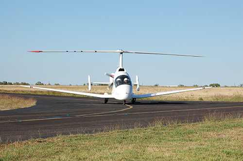
More than an autogyro: The innovative Personal Air Vehicle (PAV), designed and built by Carter Aviation Technologies, combines fixed-wing aircraft design with a rotor that delivers vertical takeoff and landing (VTOL) ability and demonstrates the company’s Slowed Rotor/Compound (SR/C) technology for greatly reduced drag. The all-carbon composite aircraft is poised for commercialization, after 21 years in development. Source (all photos): Carter Aviation Technologies
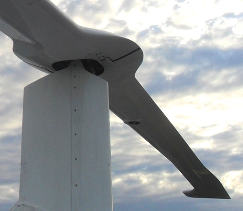
Strong but flexible blade connection: The rotor blade assembly is the most complex part of the aircraft, and incorporates stainless steel tip weights and leading-edge extensions. To handle the rotor’s high centrifugal loads, a monolithic carbon flex beam holds the two blades together, across the mast.
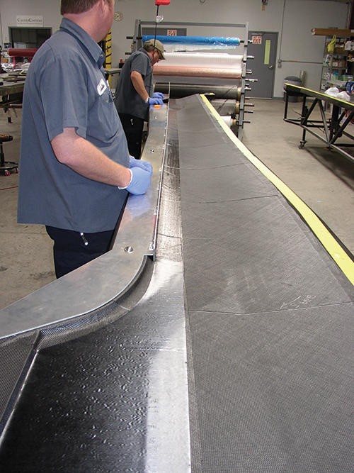
Rotor blade skin layup: Workers fabricate one of the demonstrator’s rotor blade skins. The ±45° prepreg plies employed for torsional stiffness are clearly visible.
CarterCopter copy one: The first Carter prototype is pictured here. The CarterCopter Technology Demonstrator (CCTD) used a company-designed composite propeller, had a twin-boom configuration, and featured a pressurized cabin for high-altitude flight.
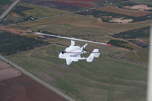
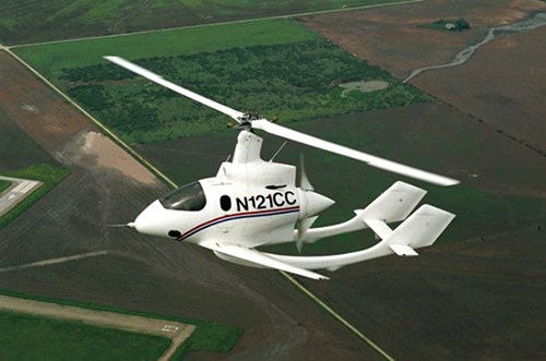
Personal Air Vehicle … in the air: The new PAV is currently flying and, according to Carter Aviation, attracting attention from potential OEMs. The technology is reportedly scalable for potential military, transport or utility applications.


Transformation in any industry takes time, but it can be an especially long process in the aerospace industry. That’s something Jay Carter, Jr., president and CEO of Carter Aviation Technologies (Wichita Falls, TX, US) knows only too well. But 21 years of research and development might finally be paying off: OEMs are beginning to show serious interest in Carter’s intriguing flight concept, its trademarked Slowed Rotor/Compound (SR/C) demonstrator, which “would be impossible to execute without composite materials, particularly carbon fiber,” he asserts. The company currently has a flying demonstrator, called the Personal Air Vehicle (PAV), and, quips Carter, “We’re getting people’s attention!”
Jay Carter’s background spans entrepreneurial experiences in aviation, rotorcraft, composite materials and, early on, wind energy. He helped found Carter Wind Energy in the early 1970s. The company pioneered a two-bladed, downwind, self-erecting turbine design that, Carter claims, produces four times the energy per kilogram of equipment weight compared to current three-bladed wind turbines. His blade designs incorporated concepts used in the helicopter industry, he says, and benefited from his personal experience working on the XV-15 tiltrotor at Bell Helicopter Textron Inc. (Ft. Worth, TX, US).


After he sold his wind turbine company to European investors, Carter started his aircraft company in 1994, believing that his idea for a better autogyro-type craft was worthy of development. The resulting CarterCopter is a fixed-wing, propeller-driven airplane with an attached rotor that adds vertical capability to the craft’s fixed-wing speed and efficiency. Like an autogyro, the CarterCopter uses an unpowered rotor in flight together with a propeller for forward thrust. But unlike most autogyros, which require runway takeoff, Carter’s SR/C technology enables vertical takeoff and landing (VTOL) capability. The transformative key to the technology is that it decouples the rotor from power prior to lift off, yet maintains blade rotation to provide lift for vertical takeoff, then slows the rotor as the wing contributes lift during the transition to forward flight, reducing almost all drag on the rotor blades.
“Slowing the rotor all but eliminates its contribution to drag in flight, and you’re back to a pure fixed-wing aircraft. It is VTOL performance without the debilitating impact of an open rotor system with its associated drag and cruise inefficiency,” says Jon Tatro, Carter’s president of international affairs.
A clean-sheet design blends the best of both worlds
The key to the aircraft’s design is the “slowed rotor,” which involves several concepts. First, helicopters are great at providing lift at low speeds, and during hover, but at high forward speeds, the retreating rotor blade — that is, the blade moving toward the rear of the aircraft during forward flight — can actually stall, creating an unstable flight condition, essentially limiting a helicopter’s forward speed. In contrast, SR/C rotors are unloaded in flight, avoiding retreating blade stall by transferring lift to the wing. Drag on a helicopter’s blades increases significantly at higher speeds, especially when high rpm is maintained. Slowing the rotor dramatically reduces this drag, says Carter, but “required solving several technical issues.”
“While many have looked into stopped rotors in flight, the drag savings over a slowed rotor is minimal, and you lose centrifugal force that helps maintain rotor stiffness,” explains Carter. “You would have to build the rotor much heavier than an SR/C rotor, offsetting the minimal drag savings.” Finally, fixed-wing aircraft have great cruise efficiency, and faster speeds than a helicopter, but their wings are over-designed and larger than needed for cruise flight. This is to ensure that the wings provide sufficient lift during the slow flight regimes of takeoff and landing: “Most airplanes also have some type of device, such as flaps, to augment lift at low speed, but which add weight and complexity to the wing,” explains Carter.
Carter addressed all of these competing tradeoffs with a clean-sheet design, creating an aircraft that incorporates a lightweight, high-thrust, pusher propeller, a high-aspect fixed wing, and a rotor with weighted tips (more on that below). The rotor is spun up on the ground (with the wheels countering the rotor’s torque), then the pilot disengages the rotor power just prior to a vertical takeoff, yet the rotor is still spinning, essentially powered by its own inertia as the craft lifts off. Off the ground, the pilot engages the propeller’s forward thrust and transitions the craft to forward flight. As the wings begin to account for more of the lift the rotor is slowed by tilting the rotor mast, first aft, until auto-rotation is achieved, then forward until rotor rotation is slowed and lift is reduced to the minimum stable condition, which significantly reduces rotor drag (Carter’s SR/C rotor approach is explained
in detail here and frequently asked questions are answered here).
Says Carter, “Rotor drag at very low rotor rpm and low lift basically becomes a function of the rotor’s surface area, which is relatively small compared to an airplane wing of similar gross weight.” Without the need to power the rotor during forward flight, there is no need for the typically heavy geared transmission, tail rotor and other equipment required in a conventional helicopter. Therefore, the SR/C saves tremendous weight and complexity, while significantly reducing noise.
As a result, the SR/C aircraft reportedly delivers fuel efficiency on par with comparable fixed-wing aircraft, while delivering a higher cruise speed than comparable rotorcraft. Says Tatro, “It consumes one-third the fuel of conventional helicopters, and has an operating cost one-third of a conventional helicopter, at less than half the acquisition cost.”
Carbon fiber the key
Composites are a key enabler in the firm’s PAV flying demonstrator aircraft. Carter says that a lot of “sophisticated analysis” was devoted to structural design to develop the rotor, wing and fuselage elements. The original CarterCopter Technology Demonstrator was fabricated and extensively flight-tested from 1998 to 2005. The current PAV incorporates many “lessons learned” from the original, adds Carter. Essentially all-composite, the PAV’s rotor blades (including skins and internal structure), wing structure, fuselage and empennage are sandwich constructions made, in-house, using primarily carbon/epoxy prepreg faceskins and closed-cell polyvinyl chloride (PVC) foam core. Prepreg material suppliers include A.P.C.M. LLC (Plainfield, CT, US), Park Electrochemical Corp. (Melville, NY and Newton, KS, US) and Barrday Advanced Material Solutions (Cambridge, ON, Canada).
Carter says carbon fiber was selected to achieve the lowest possible weight, and for its excellent fatigue performance. The company also produced the parts on its own carbon composite tools, to ensure similar coefficients of thermal expansion (CTEs) for the tools and parts.
The aircraft’s most complex assembly is the rotor. Carter explains that each 6.9m-long blade was constructed with 34 kg of stainless steel weights at the rotor tips, with the tips shaped with a leading edge extension (see second photo down, at left). The purpose of the weights is multi-fold. First, they generate the high centrifugal force that maintains blade rigidity, “like a rock on a string,” he says. Weight position combined with the blade shape maintains rotor stability at high speeds and low rotor rpm. Finally, the weights maintain rotation after power is cut during take-off.
“With the weight at the tips, our high-inertia rotor develops a lot of energy without the need for a large drive motor. It’s that energy that allows the aircraft to ‘jump’ into the air on takeoff, with simultaneous increased pitch on the propeller allowing transition to forward flight.” (The company also offers technology for a second, hovering variant that powers the rotor for takeoffs and landings, like a conventional helicopter.)
To handle the tip weights and high centrifugal loads, the two rotor blades are tied together across the rotor mast by a monolithic (uncored) box-beam-shaped carbon flex beam. “Spars are typically thought of as carrying weight and lift-induced bending loads,” explains Jeff Lewis, engineering manager, “so we called this structure a flex beam, since it’s carrying centrifugal force and edge-wise bending.” The flex beam spans the inboard portions of both blades and is designed with high edge-wise stiffness: “The first modal frequency is higher than the fastest rotation of our rotor, ensuring that no resonance will occur, thanks to the very stiff flex beam,” adds Lewis.
The flex beam was filament wound, Carter explains, combining axial fibers with ±45° fibers in a proprietary, in-house process that places all of the fibers with the same pre-tension, or pre-load — something he says is difficult to do but which provides better tensile performance. But, despite having high edge-wise stiffness, Carter says that the beam’s caps are “torsionally soft,” employing spread unidirectional fibers. This flexibility in the caps reportedly allows the rotor blades to change pitch via shape change — that is, the design does not incorporate the mechanical pitch-change hardware typically seen on helicopters. And that offsets what would otherwise be extra weight. “Our rotor blade weighs the same as a typical helicopter blade,” he explains, “even with the tip weights, because we can eliminate these ancillary mechanical systems.”
In addition to the filament-wound flex beam, the mostly hollow rotor blades also have a main spar running the length of the blade to carry centrifugal loads, and smaller, leading-edge and trailing-edge spars that run the length of the blade for additional edgewise stiffness. For high torsional stiffness, the PVC foam-cored outer (aero surface) skins were fabricated with a minimum of five plies of ±45° prepreg, with additional plies added to specific regions as required. Rotor blades can be disassembled for transport, with metal pin joints at a point one-quarter of the distance from the rotor mast, at the ends of the internal flex beam; removing the metal pin allows for removal of the outboard blade sections. Carter says the rotor blades can carry “huge” loads, based on static testing to failure, at more than 2.2 million N of applied force.
The PAV’s upper and lower sandwich construction wingskins comprise five plies of ±45° prepreg on the outer (aero) surfaces, with one ±45° ply on the inner surfaces, which are exposed to fuel, because the wings double as the craft’s fuel tank. Lightweight composite ribs inside the wings provide necessary structural support and also act as fuel baffles.
The fuselage was fabricated in two halves, and after cure, says Carter, the layup tools doubled as bond tools. An epoxy adhesive was used to bond the left- and right-hand halves together, with a wet-out carbon ply applied over the adhesive seam. Says Carter, “We used a flexiblizer in the adhesive for better toughness.”
The company also has a composite propeller design, one that was used on the original demonstrator but not, currently, on the PAV. At one-quarter the weight of typical composite propellers, Carter says it was designed for significantly higher thrust than engine/prop designs available at the time, and that it will be resurrected, going forward.
Growing interest, scale-up coming
Given the PAV’s success and demonstrated abilities, the company’s focus is shifting to generating interest with OEMs and getting the aircraft into production. Carter envisions scaled-up designs of the PAV for possible military, transport or utility applications, where the SR/C technology would be licensed to a manufacturer. He reveals that in mid-August, he hosted a major aerospace company that is evaluating the potential of SR/C technology in the marketplace, and working toward a decision to develop a product: “The aerospace company sent a gaggle of folks with them, including individuals focused on technical aspects, business development and, of course, test pilots,” claims Carter. “We flew a bunch of them in the aircraft, showing our jump takeoffs, and did a flyover with the 45-ft diameter rotor slowed to 112 rpm — it was unbelievably quiet. The meeting went extraordinarily well.”
After more than two decades of development, the company has hired two new test pilots to handle demo demands and Carter says he’s contemplating a long-distance, nonstop flight soon to showcase the PAV’s range and speed: “We’re ready to show off, now!”
See the PAV demonstrator in flight online, in the following videos:
Smithsonian Channel | www.youtube.com/watch?v=0_35146K1rg
Slowed rotor, external view | http://youtu.be/ono8ztoTCXk
Slowed rotor, cockpit view | http://youtu.be/_c_9zoXzd88
PAV takeoff and landing, external and cockpit views | https://youtu.be/7TyxUZjP_PE


Related Content

ECOHYDRO project to enable recyclable composites for hydrogen storage
With the involvement of two schools from the Institut Mines-Télécom, the 4-year project aims to improve the intrinsic properties of a composite material based on Elium via four concrete demonstrators.
Read More
Honda begins production of 2025 CR-V e:FCEV with Type 4 hydrogen tanks in U.S.
Model includes new technologies produced at Performance Manufacturing Center (PMC) in Marysville, Ohio, which is part of Honda hydrogen business strategy that includes Class 8 trucks.
Read More
NCC reaches milestone in composite cryogenic hydrogen program
The National Composites Centre is testing composite cryogenic storage tank demonstrators with increasing complexity, to support U.K. transition to the hydrogen economy.
Read More
Infinite Composites: Type V tanks for space, hydrogen, automotive and more
After a decade of proving its linerless, weight-saving composite tanks with NASA and more than 30 aerospace companies, this CryoSphere pioneer is scaling for growth in commercial space and sustainable transportation on Earth.
Read MoreRead Next

“Structured air” TPS safeguards composite structures
Powered by an 85% air/15% pure polyimide aerogel, Blueshift’s novel material system protects structures during transient thermal events from -200°C to beyond 2400°C for rockets, battery boxes and more.
Read More
VIDEO: High-volume processing for fiberglass components
Cannon Ergos, a company specializing in high-ton presses and equipment for composites fabrication and plastics processing, displayed automotive and industrial components at CAMX 2024.
Read More
All-recycled, needle-punched nonwoven CFRP slashes carbon footprint of Formula 2 seat
Dallara and Tenowo collaborate to produce a race-ready Formula 2 seat using recycled carbon fiber, reducing CO2 emissions by 97.5% compared to virgin materials.
Read More