Fiber-metal laminates in the spotlight
Interest in FMLs is growing again as aeroengineers search for lightweight solutions adaptable to new narrowbody commercial aircraft.
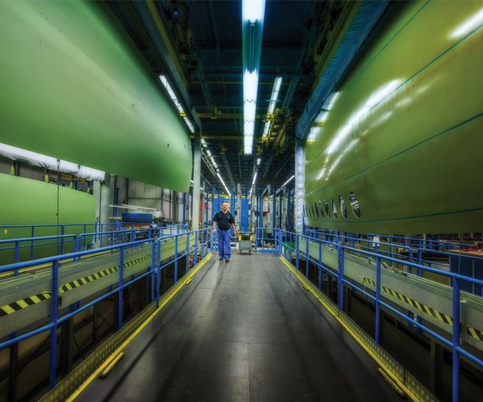
There is no doubt that composites have earned their way into aerospace structure, as evidenced by The Boeing Co.’s (Chicago, IL, US) and Airbus’ (Toulouse, France) leap to composite wing and fuselage structures in the 787 and the A350 XWB, respectively. But recent questions about whether those same composites could be practical replacements for the thin aluminum fuselage skins found on aging narrowbody, single-aisle aircraft, such as Boeing’s 737 and the Airbus A320, have helped revive interest in already certified hybrid materials called fiber-metal laminates (FMLs) that combine metal and composite products and are designed to take advantage of the best qualities of each material class.
Genesis in fatigue performance
Riveted aluminum aircraft structures are vulnerable to fatigue cracking. FMLs were the result of a long investigation into ways to improve aluminum fatigue performance by bonding multiple thin layers of the metal with polymer adhesives. “Our company began developing metal bonded structures, consisting of thin aluminum sheets hot-bonded together, from the early 1950s, a technique that helped reduce weight and crack growth in aircraft,” says Maarten van Mourik, director of programs at GKN Aerospace’s (Redditch, UK) Fokker business (Papendrecht, The Netherlands).
The transition to a metal/composite hybrid, however, came about 30 years later, during work done by Fokker in cooperation with researchers at Delft University of Technology (TU Delft, Delft, The Netherlands). “To further increase fatigue performance, in the early 1980s, our technologists started investigating the addition of fibers to the adhesive bond lines.” The Fokker/TU Delft collaboration led to the concept of fiber-metal laminates (FMLs) as a distinct class of hybrid composites for aircraft structure.
After the demise of the original Fokker Aircraft company in 1996, focused research continued at TU Delft, in close cooperation with Alcoa (New York City, NY, US), Dutch chemical company Akzo Nobel Polymer Chemistry (now AkzoNobel, Amsterdam, The Netherlands)
and Airbus, with support from the Dutch government as well as European Union-supported projects. These activities were vital in evolving the FML concept to a level where it ultimately became a new structural material with design principles that gave it distinct advantages over aluminum, says van Mourik.
FMLs generated considerable interest in the aircraft industry when introduced in the late 1980s, due to their performance and weight savings potential. They were ultimately certified and adopted by several airframers in primary structure. First known as Arall (Aramid Reinforced Aluminum laminate) aimed at wing applications, then as Glare (Glass fiber-reinforced aluminum) for fuselage structure, and more recently as High Static Strength Glare, FMLs have been investigated by numerous OEMs, including Boeing, which considered FMLs as reinforcement material for the longeron of the A10 close air-support aircraft. Lockheed Martin (Bethesda, MD, US) successfully investigated the potential of Glare FMLs for weight savings and increased life for lower wingskins on Hercules C130 aircraft. FMLs also found use in the C130 flaps, in the aft cargo door of the McDonnell Douglas C-17, in the Airbus A400M frames, and, beginning in 2000, in the Airbus A380’s upper fuselage and tail leading edges.
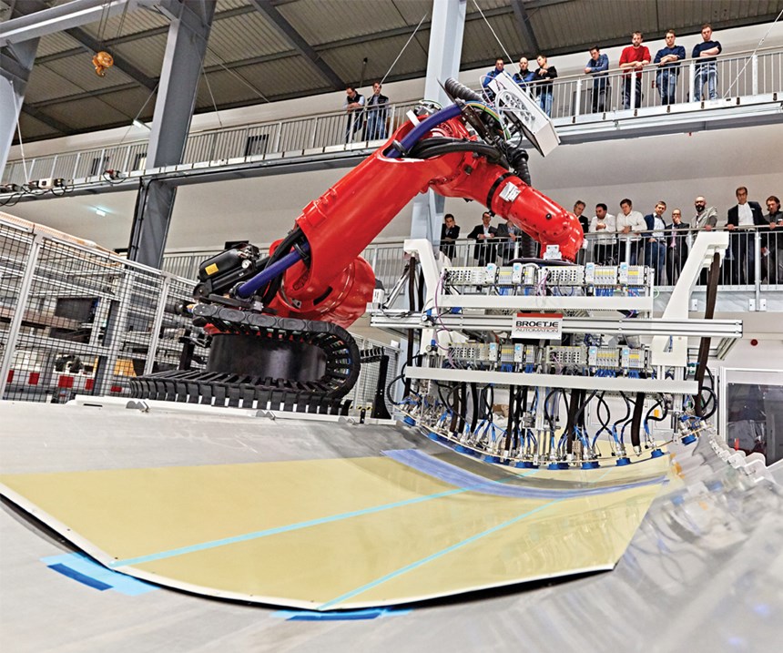
But van Mourik points out that the original purpose for which these hybrid laminates were developed is still a concern: “Fuselage structure, as shown by the Aloha Airlines Flight 243 accident (see Learn More, p. 93), is susceptible to fatigue damage and failure due to pressurization cycles, and can really benefit from FMLs.” And as OEMs begin to evaluate materials for new narrowbody commercial aircraft, interest in this material has re-ignited. In response, GKN Aerospace’s Fokker business is developing, with partner firms Airbus, Premium AEROTEC GmbH (Augsburg, Germany)and Stelia Aerospace North America (Toulouse, France, see Learn More), both of which also produce FML panels for Airbus, automated manufacturing methods to meet the anticipated demand.
A synergistic combination
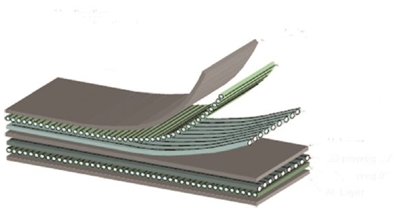
Fokker’s FMLs address fatigue by bonding alternating layers of treated aluminum sheet and fiber/epoxy prepreg (see Fig. 1). When TU Delft researchers substituted glass fiber for the aramid fiber employed in the first-generation Arall panels of the 1980s to create Glare, the choice proved serendipitous. The S-2 Glass, sourced from AGY Holding Corp. (Aiken, SC, US), was more compatible with aluminum properties, and improved the laminate’s fatigue performance as well as impact, corrosion and fire resistance, without hindering the aluminum’s good lightning strike properties. The glass layers stopped crack growth, eliminating the need for expensive titanium crack-stopper straps previously used at highly loaded airframe locations. And, the glass fibers increased the material’s elastic strain capacity, enabling it to absorb more impact energy. Further, impact damage resulting from ground operations or abrasion would be visible on the surface, something not always true in the case of composites-only fabrication.
Today, the structure and the manufacturing process of FML have evolved. Van Mourik and Fokker employees Pim Tamis, Cees van Hengel and Peter Kortbeek described the following materials and process steps developed and currently used to form the A380 panels. FML manufacture starts with rolls of bare aluminum sheet from a variety of suppliers, 1.2-1.5m wide, with sheet thickness ranging from 0.3-0.4 mm. GKN Aerospace’s Fokker business uses both Al2024 aerospace-grade aluminum, an aluminum-copper-magnesium alloy with high corrosion and fatigue resistance, and Al7475 aluminum, the highest-strength and highest-toughness alloy available, which comprises aluminum-zinc-copper-magnesium, for its current FML offerings. Airbus, van Mourik notes, also has successfully investigated aluminum-lithium FML, for maximum performance, with Dutch technology partners. For unidirectional glass fiber/epoxy prepreg, the most common supplier is Solvay Composite Materials (Alpharetta, GA, US) from its Wrexham, Wales, UK, facility.
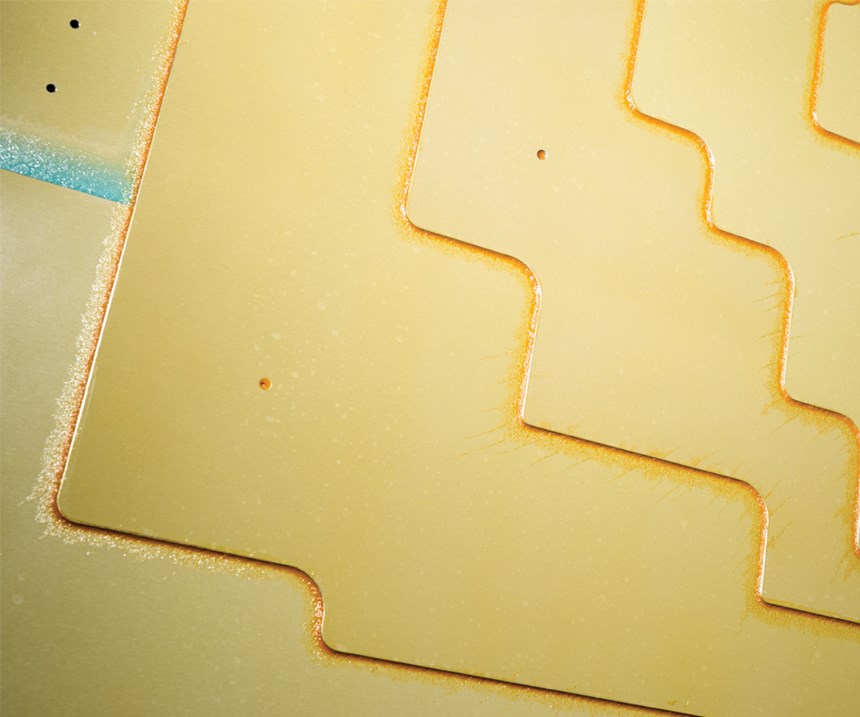
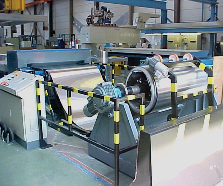
In the initial step, a custom-built machine decoils the aluminum from rolls, flattens the sheeting and cuts it to lengths of up to 11m for some panels. Next, the cut sheets are milled in accordance with the overall design. For example, cuts are made for window openings and to define the outlines of stringers or ribs that subsequently will be bonded to the panel. Milled sheets are then transferred via a handling system to the chemical treatment area, where degreasing with a solvent is followed by “pickling” to remove any oxide layers on the aluminum. Sheets are then anodized in an electrochemical bath of chromic acid, which creates a new, controlled oxide layer, which ensures a good surface for bonding. (The company notes that it is working on next-generation “greener” chemical options for anodizing.)
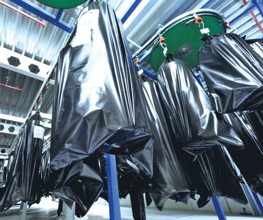
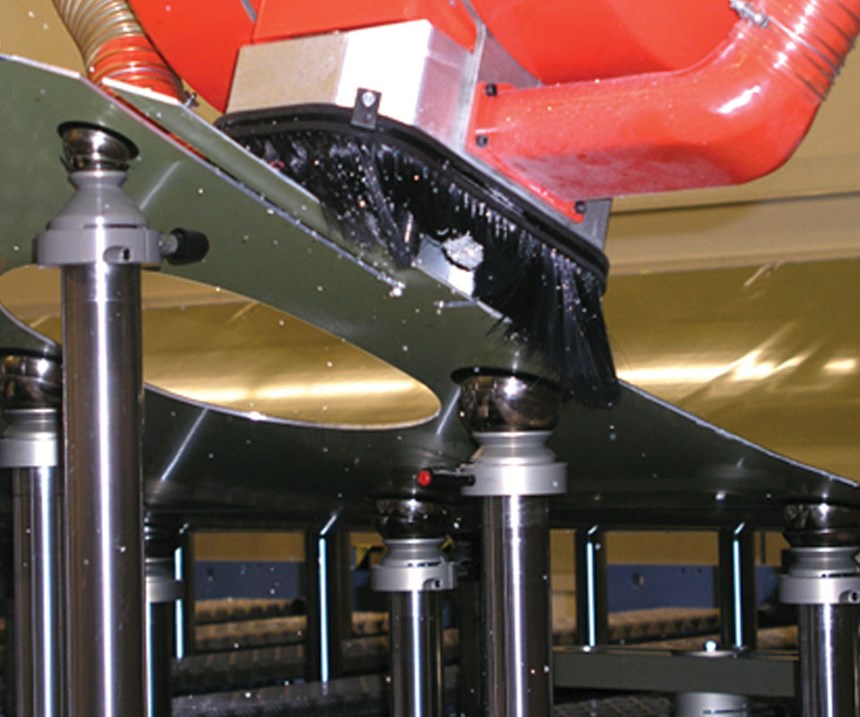
Next, the treated sheets are transferred to an area where automated equipment sprays them with primer, a step called bond priming. Primed, cut sheets are re-rolled, with a protective paper layer preventing metal-to-metal contact, and covered in protective black plastic for storage until needed in fabrication.
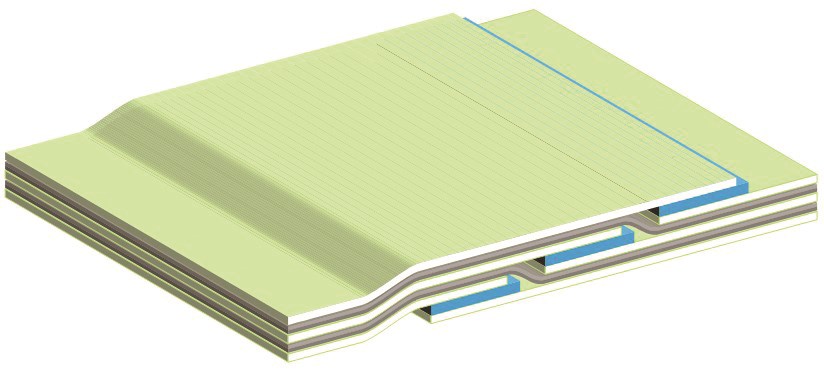
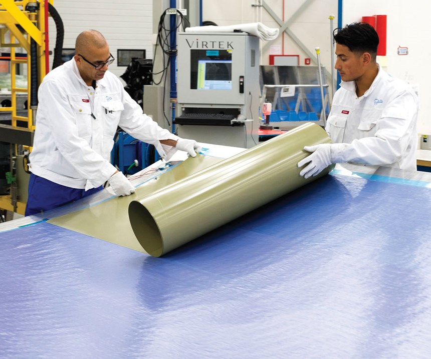
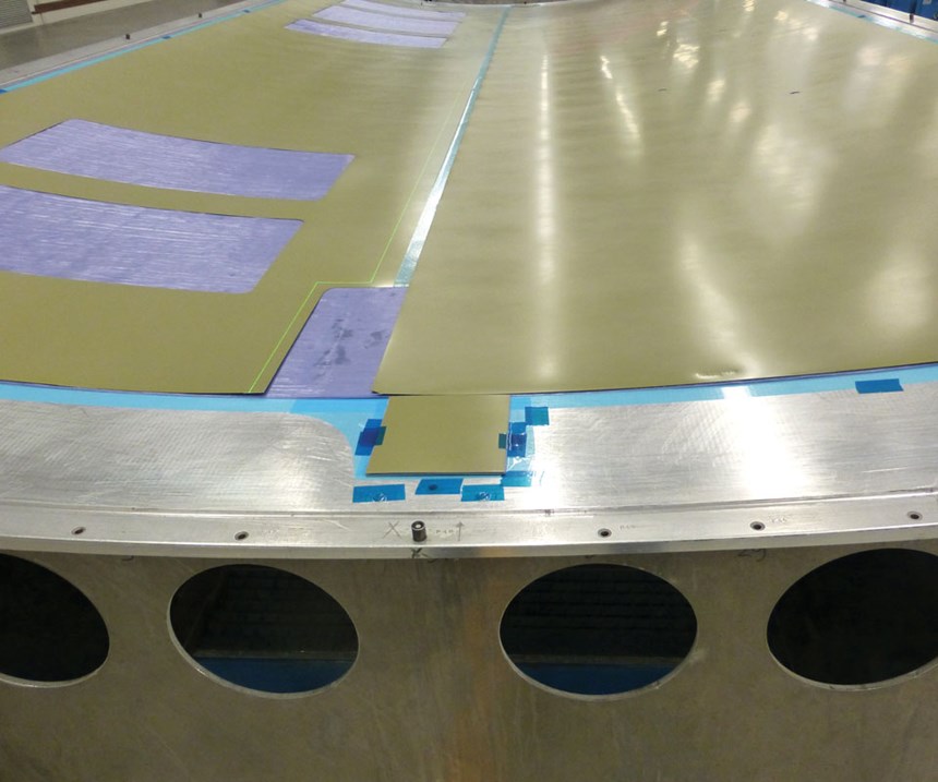
Panel layup occurs by hand in aluminum female panel molds (for large, relatively flat panels) or on jigs for smaller, more complex parts with cutouts. Laser projection systems, sourced from Virtek Vision International Inc. (Waterloo, ON, Canada), guide layup by indicating exactly where sheet overlaps will occur, in coordination with registration pins on the jigs and molds. A prepared aluminum sheet is first down in the mold and, depending on the size of the final panel, is overlapped with an additional sheet or sheets by approximately 25 mm. Epoxy film adhesive (the same epoxy as employed in the glass fiber prepreg) in the overlap holds the splices together. This allows considerably larger panels than standard aluminum plate aircraft builds, explains van Mourik.
“Splicing joins the sheets together for much larger panels, which helps simplify aircraft manufacture since fewer panels are needed. We can produce panels up to 44m2,” he says, “and are really limited only by the size of the autoclave.” Fig. 2 shows how panel designs can be built up by splicing the FML laminates with additional epoxy film adhesive, to create larger and/or complexly curved parts, and, he adds, to optimize panel weight distribution.
Glass/epoxy prepreg in widths of 460 mm is placed over the initial aluminum sheet in the orientations dictated by the design. As shown in Fig. 1, the glass prepreg plies are typically oriented in a 0°/90° configuration, but any fiber orientation can be employed to meet a specific design case. Prepreg roll edges are typically butted to cover larger panels, but in some cases, controlled overlaps are allowed for double-curved panels. Layup continues, with alternating plies of aluminum and prepreg, as required, to build up the panel’s thickness. The thinnest FML laminate is 2/1, or two aluminum layers sandwiching a prepreg layer; much thicker laminates up to 33/32 are possible for highly loaded areas.
“The most common FML designs are 3/2, 4/3 and 5/4 laminates,” explains van Mourik. “The benefit of these designs is that the fibers take the load if the aluminum microcracks, which suppresses crack growth. We can design panels of varying thickness by fuselage location, depending on the loads, for example, around windows or doors or at frame locations where fasteners will be used — additional layers can be added internally, or additional FML layers can be bonded on the outside of a panel, as doublers.”
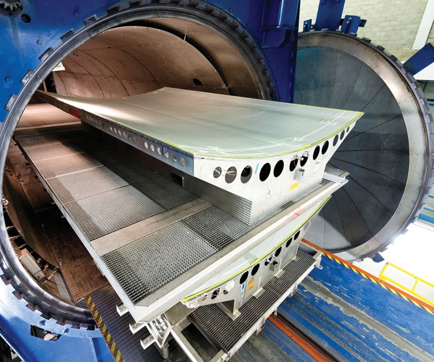
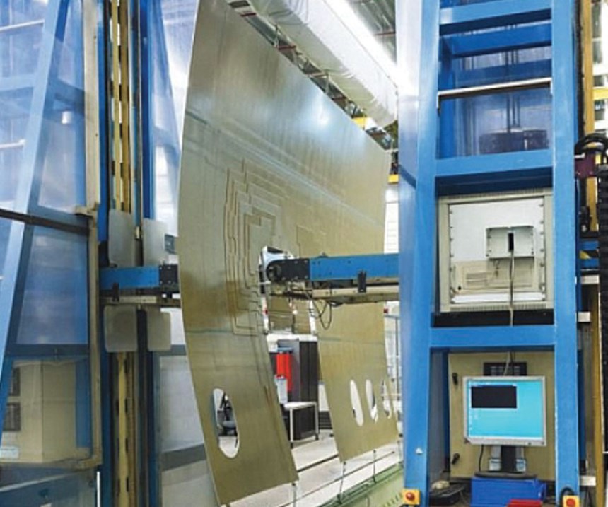
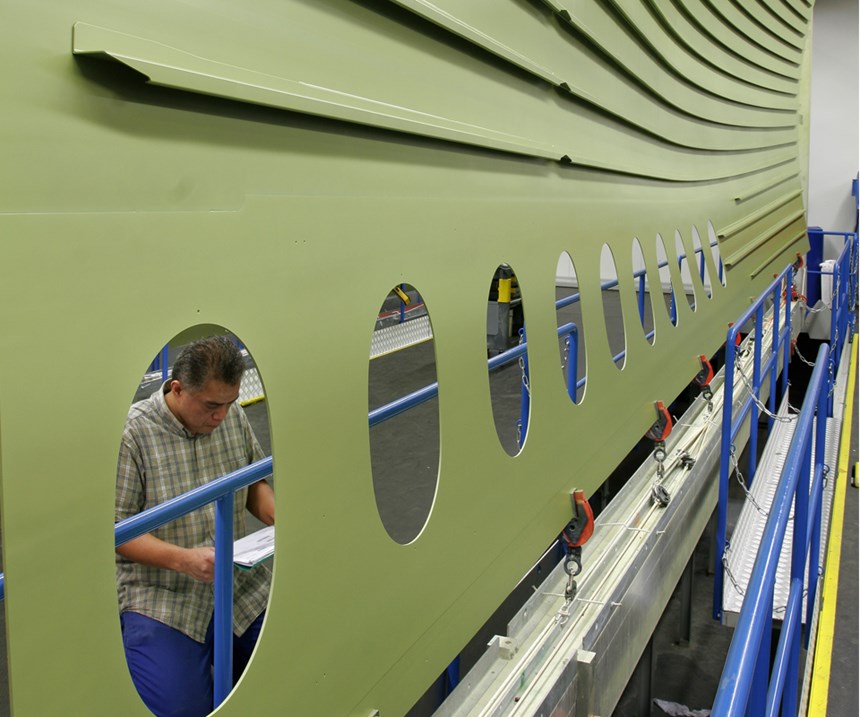
Layups are vacuum bagged, then transferred to the autoclave. Cure takes 3.5 hours at 120°C for standard Glare (up to 180°C for High Static Strength Glare), with a ramp rate of 2-5°C/min at 11 bar. Following cure and demolding, panels undergo C-Scan inspection, followed by another round of milling, to ensure a smooth surface. Finally, panels are painted, then expedited to customer assembly locations.
A new generation of hybrid material
FML panels are ultimately thinner than aluminum alone because they perform better in fatigue — so weight is at least 15% to as much as 25% less than aluminum alone. Because of the lighter weight, panels can be made larger, spanning larger areas of the fuselage. Larger, thinner panels provide cascading benefits throughout the airframe, because fewer brackets, supporting ribs and fasteners are required, and assembly can be accomplished faster. The use of Glare on the upper fuselage of the Airbus A380, for example, saved more than 1,000 kg, compared to aluminum, and the material has performed better than aluminum alone with regard to lightning strike and under the tension loads imposed on the fuselage by passenger cabin pressurization cycles during aircraft service.
Van Mourik points out that the economics of FMLs fit best with heavily scheduled commercial aircraft, where “FMLs reduce cost of ownership for airlines because of better fatigue performance, and much longer inspection intervals can be put in place, which saves on maintenance.” Longer fatigue life and weight savings, he notes, aren’t as critical to owners of business jets or general aviation aircraft.
There is one sticking point: For now, Airbus is the sole customer for glass-reinforced FMLs, due primarily to arrangements made with the OEM when it invested in the material’s development. Also, patents have limited its applications to aircraft built in Europe, although that situation might change, going forward.
Nevertheless, van Mourik asserts, “We believe the properties of FML and its additional interlinked advantages make it the best fuselage material, with the best design principle.” And it may be the ideal material choice for new narrowbody aircraft fuselage structure, he explains. “Fiber-reinforced polymer composites require a minimum thickness to resist damage,” he points out, “so while they made sense for larger twin-aisles, they are not the logical choice for smaller narrowbody craft,” says van Mourik, adding, “That minimum skin thickness takes away composites’ weight advantage.”
FMLs also offer some distinct processing and cost advantages. Comparing the manufacturing process of FMLs with current composites, FML manufacture employs aluminum molds where today’s large, typically carbon fiber-reinforced polymer (CFRP) structures often require costly Invar tooling. Further, FML cure temperatures are much lower than those required for CFRP. This, in combination with the lower raw material cost and greater automation, can bring FML applications for primary structures into the cost range of aluminum, which is at least half that of a composite design.
FMLs, like metals, also avoid the add-ons needed for composites to provide electrical functions, such as lightning strike mesh, electrical shielding and return paths.
FML manufacture will become less expensive, going forward, as GKN Aerospace’s Fokker business continues work on an industrial automation project, with Airbus Premium Aerotec GmbH and Stelia Aerospace. Smart, automated and robotized production technology will enable higher-volume production rates and increase affordability for OEMs.
The company continues to improve FML with “disruptive” concepts, including embedding heating elements for deicing, embedding antennae within the laminate to replace drag-inducing exterior antennae, and producing “wired” FML with embedded electrical systems for structural health monitoring.
Concludes van Mourik: “Our automated concepts will continue to bring costs down. FML has huge innovation potential for functional integration of systems.” For a company that believes in taking advantage of what each of the available aerospace materials can offer a customer in a finished product and desires to develop optimized production processes, FMLs offer an ideal opportunity to cultivate both.
Related Content
Automotive chassis components lighten up with composites
Composite and hybrid components reduce mass, increase functionality on electric and conventional passenger vehicles.
Read MoreNovel composite technology replaces welded joints in tubular structures
The Tree Composites TC-joint replaces traditional welding in jacket foundations for offshore wind turbine generator applications, advancing the world’s quest for fast, sustainable energy deployment.
Read MoreReal-time assessment of thermoset composites curing
The combination of material state management (MSM) software and an encapsulated sample rheometer (ESR) enables real-time cure recipe management or cure model development inside the autoclave.
Read MoreUnderstanding vacuum bagging layers in production, repair
Recognizing the functions of each layer in a vacuum bag schedule can help users discover what vacuum bag schedules work best for their application.
Read MoreRead Next
Plant tour: Daher Shap’in TechCenter and composites production plant, Saint-Aignan-de-Grandlieu, France
Co-located R&D and production advance OOA thermosets, thermoplastics, welding, recycling and digital technologies for faster processing and certification of lighter, more sustainable composites.
Read MoreDeveloping bonded composite repair for ships, offshore units
Bureau Veritas and industry partners issue guidelines and pave the way for certification via StrengthBond Offshore project.
Read MoreAll-recycled, needle-punched nonwoven CFRP slashes carbon footprint of Formula 2 seat
Dallara and Tenowo collaborate to produce a race-ready Formula 2 seat using recycled carbon fiber, reducing CO2 emissions by 97.5% compared to virgin materials.
Read More



.jpg;maxWidth=300;quality=90)


