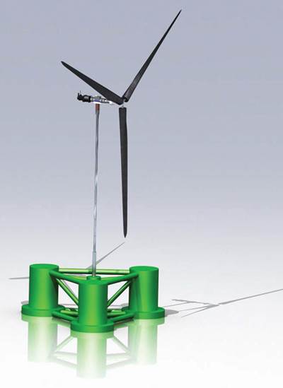
GFRP enables first grid-connected U.S. floating wind turbine
Composite tower on 1:8-scale system reduces hull size/weight and helps mitigate the overall cost of electric power generation.
Engineering challenge:
Design a floating foundation and tower that will minimize the costs of materials, construction and installation of a 1:8-scale prototype wind turbine in a deepwater offshore environment.
Design solution:
Coupled aeroelastic/hydrodynamic modeling yields a composite tower half the weight of steel, reducing hull foundation weight by two to three times the tower’s weight savings.
Although the business case for offshore wind farms is compelling (see “Wind over deep water,” under Editor's Picks," at top right), installing offshore turbines is no easy task. Even in shallow coastal waters, it’s expensive. Large turbine installation vessels (TIVs), with jackup technology and massive cranes, transport tower and turbine components to the site, then hammer steel piles into the seabed, assemble the steel tower, and lift and install the turbine and rotor. Deep water along many coastlines, however, precludes the relative simplicity of a steel-pile foundation. As developers confront regions where shallow water is scarce, a different approach is necessary — specifically, floating foundations.
Floating turbine concepts, in fact, are abundant, says Main(e) International Consulting LLC’s (Bremen, Maine) offshore wind expert Annette Bosler. “This year may become a boom year for various European launches, if projects stay on track,” she points out. “Whoever likes to refer to floating offshore wind technology as ‘niche’ and a long way off may want to reconsider that statement.”
In anticipation of this boom, the University of Maine’s (Orono, Maine) Advanced Structures and Composites Center (ASCE) headed a consortium of companies called DeepCWind and began to develop the concept four years ago. “When we started work, nothing like this … had been done before,” says consortium leader and UMaine professor Dr. Habib Dagher.
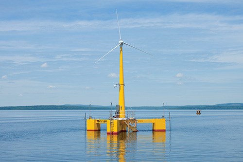
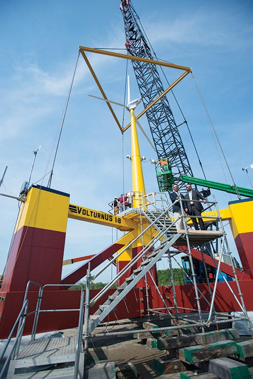
DeepCWind plans to field a grid-connected, pilot floating wind farm in coastal Maine by 2017. In its first step toward that goal, ASCE launched a 1:8-scale floating turbine research prototype last year, funded by a 2012 U.S. Department of Energy (DoE) grant and featuring a composite tower built by consortium partner Ershigs (Bellingham, Wash.).
Coupled models
Floating foundations presented DeepCWind a complex problem: how to understand, and then design for, the interaction between aeroelastic loads — caused by the wind and rotor movement — and the hydrodynamic loads imposed by the water. Together, wind and water impose different loads on foundations, towers and turbines than those experienced by onshore turbines. And, says Dagher, “The physics of a floating, rotating turbine affected by wave motion are harder to work out than for land-based systems.”
A computer analysis was undertaken in partnership with the National Renewable Energy Laboratory (NREL, Golden, Colo.), using NREL’s open-source coupled model, called FAST. (For more information about FAST click here.) FAST simultaneously modeled the coupled aerodynamic, hydrodynamic, control system and structural response of offshore wind systems.
The consortium also used experimental data collected from testing the impacts of wind and waves on small-scale (1:50) floating turbines in the experimental wind and wave basin at the Maritime Research Institute Netherlands’ (MARIN, Wageningen, The Netherlands). Dagher’s group analyzed wave amplitudes/frequencies and passage rates, asking how quickly the waves move past the foundation, how they interact with the floating foundation, and whether those frequencies would mirror the vibration frequencies experienced by the tower as the rotor turns.
The tower design had to account for a variety of loads, including buckling, bending, wind shear and torsional loads. “The FAST model, together with our MARIN data, told us what accelerations the tower would see, the stresses along its length and helped us size the tower section to withstand the loads,” explains Dagher. With noteworthy foresight, Dagher’s group modeled not only the 1:8 scale VolturnUS system, but future full-scale 4.5-, 6- and 8-MW floating turbine designs as well.
Modeling also exposed the relative merits of mass above and below the water line. “We worked on reducing the system mass above the water as much as possible to reduce the loads that ... would occur on both the tower and the floating foundation,” says Dagher, noting that this strategy would “minimize the cost of a platform that could survive.” A 6-MW turbine-rotor assembly, for example, can weigh nearly 800,000 lb (364 metric tonnes). To support that at the design hub height of 300 ft/92m, Dagher explains, would require a steel tower weighing a whopping 901,690 to 1.2 million lb (409 to 545.4 metric tonnes), with a base about 30 ft/9.2m in diameter, and an exceedingly large hull. But the composite tower proposed by UMaine and Ershigs would support the modeled loads at a little more than half the weight of steel. The resulting weight reduction in the floating hull is two to three times the tower weight savings. Further, Dagher believes, based on lab fatigue testing, that its corrosion resistance makes a 60-year design life feasible, compared to the typical 20 to 25 years for a conventional steel tower. “Even though composites are more expensive than steel, the value they bring to the entire floating turbine project over its lifetime, and especially the cost savings in the hull design, can pay for the added costs.”
“Composite materials offer compelling advantages, particularly for offshore floating wind power,” notes Ershigs’ VP Steve Hettick.
Towering advantages
A patent is pending on the consortium’s tower design and, therefore, its fiber architecture and fabrication process are deemed proprietary. But Dagher stresses that Ershigs is using “well-established methods and well-known materials” to keep the project’s costs as low as possible for the 1:8-scale tower and future full-scale towers. Material suppliers included Ashland Performance Materials (Columbus, Ohio), PPG Industries (Cheswick, Pa.) and VectorPly Corp. (Phenix City, Ala.). He does say that the composite tower’s wall thickness is comparable to that of a steel tower sized to meet the floating platform’s loads. Hettick adds that the coupled model output also identified frequency harmonics to avoid and other safety factors. These prompted Ershigs’ selection of E-glass laminates with considerable axial reinforcement for the VolturnUS tower and larger towers to come.
Although the 1:8-scale tower was made in one section, a monolithic design isn’t feasible for the proposed 280-ft/86m tall tower that will support 6-MW floating turbines, says Hettick. For it, Ershigs will produce “can” sections similar to those used to assemble a steel tower. Built up from large infused curved panels arranged, according to the patent, around a rotatable mandrel, they’ll be joined to form a cylindrical section via a proprietary winding process. Finished cans will be bolted together close to the launch site, avoiding truck transport issues that would be raised by larger assemblies. “It’s not a radical concept, it is a proven technology,” says Hettick. “The industry is comfortable with bolting steel sections together, and it will work for composites.”
The 1:8-scale prototype’s tower supports a 20-kW turbine with a 30-ft/9.2m diameter rotor. Broader at the base and more tapered than a land-based tower, it is connected to its hull in a “similar manner to the way land-based steel towers are connected to concrete foundations,” says Dagher.
A UMaine patent also is pending on the VolturnUS hull, which comprises a three-legged arrangement of hollow, semisubmersed vertical and horizontal concrete “columns” (see drawing, p. 46). Each leg is anchored via mooring line to the seabed. Outfitted with several Webcams and more than 50 sensors that collect wave and wind data as well as tower stress and strain readings, the prototype already has witnessed a wide range of winter storms, says Dagher, and has demonstrated excellent stability and small accelerations even in turbulent seas. Hull and tower performance data have been within 5 percent of the coupled model’s predictions, he adds, which validates the design. “The data we’ve collected has allowed us to understand the platform’s, and the tower’s, performance in extreme conditions, because its smaller size means that the waves are proportionally larger in comparison,” says Dagher. “It is a very effective way to de-risk the full-scale platform design.” Consistent with the project’s goal of producing electricity at a competitive rate, he contends, “a composite tower supported by a floating concrete foundation actually made the project more economically viable.”
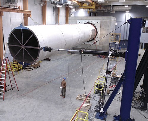
For these reasons, the much larger hulls for commercial-scale turbines will be of similar design. Ershigs, in fact, has already fabricated half-scale samples of the 6-MW turbine tower modular sections, which have been tested extensively in the UMaine ASCE laboratory for both ultimate strength and fatigue performance: “We joined sections together by bolting, as they will be on the platform, then simulated a 60-year service life,” says Dagher. “The good news is that at the end of the fatigue test, the residual strength still exceeded the initial design strength!”
Fabrication of full-scale, commercial floating turbines is planned to begin in 2016. And when they’re installed, TIV cranes and jackup barges won’t be necessary. According to Dagher, VolturnUS-style hulls, composite towers and turbines can be assembled dockside, then be towed to the deepwater farm site by conventional tugboat.
“This is a big deal,” Hettick concludes. “It’s a win-win situation for composites.”
Editor's Note: See a video of the VolturnUS launch here.
Related Content
How composites have become a necessity
Composites used to be one of many material options across industries and applications, but that's not the case anymore.
Read MoreHexagon Purus opens new U.S. facility to manufacture composite hydrogen tanks
CW attends the opening of Westminster, Maryland, site and shares the company’s history, vision and leading role in H2 storage systems.
Read MoreInfinite Composites: Type V tanks for space, hydrogen, automotive and more
After a decade of proving its linerless, weight-saving composite tanks with NASA and more than 30 aerospace companies, this CryoSphere pioneer is scaling for growth in commercial space and sustainable transportation on Earth.
Read MoreJEC World 2023 highlights: Recyclable resins, renewable energy solutions, award-winning automotive
CW technical editor Hannah Mason recaps some of the technology on display at JEC World, including natural, bio-based or recyclable materials solutions, innovative automotive and renewable energy components and more.
Read MoreRead Next
Wind over deep water
Research into floating wind turbine systems promises to expand composites to towers and platforms.
Read MoreAll-recycled, needle-punched nonwoven CFRP slashes carbon footprint of Formula 2 seat
Dallara and Tenowo collaborate to produce a race-ready Formula 2 seat using recycled carbon fiber, reducing CO2 emissions by 97.5% compared to virgin materials.
Read More“Structured air” TPS safeguards composite structures
Powered by an 85% air/15% pure polyimide aerogel, Blueshift’s novel material system protects structures during transient thermal events from -200°C to beyond 2400°C for rockets, battery boxes and more.
Read More


