
New Equipment Brings Tape Placement Within Reach Of Smaller Shops
"Right-sized" automated tape laying head is simple and affordable.


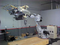
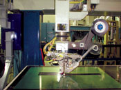
Source: Composite Systems Inc.Motoman UP200 robot with 610-mm/24-inch PFE, set up for prepreg material (system shown with arm partially extended).
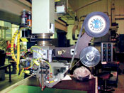
Source: Automated DynamicsStep 5: Heated nitrogen or air warms the prepreg at the nip point, for proper tack on the tool.
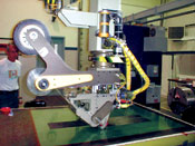
Source: Automated DynamicsStep 2: The ATL head is readied to lay material on a flat tabletop tool.
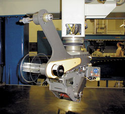
Source: Automated DynamicsAutomated Dynamics' "right-sized" automated tape laying (ATL) head has less complexity for greater efficiency.
Source: Automated DynamicsStep 4: A simple, guillotine-style cutting blade makes quick, square material cuts, without significant slowing.
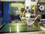
Source: Automated DynamicsStep 3: Average laydown speed of the head is 20 inches per second (ips), with return path speed close to 40 ips.
Few technologies enjoy the high-tech stature of fiber placement and tape laying. The layup speed, the complex cuts, the robotic head's axes of motion and the manufacturing efficiency are impressive — and so is the price. Depending on size, automated fiber placement and tape laying equipment can cost several million dollars per machine, a capital cost that most fabricators can't justify without a substantial production contract.
Automated Dynamics (ADC, Schenectady, N.Y., U.S.A.), a manufacturer of a range of traditional fiber placement machinery, has developed a patented concept that brings fiber and tape placement down to earth, at a more reasonable cost. The company's new "right-sized" automated tape laying (ATL) head is targeted at manufacturers who make thermoset composite parts without much curvature, in moderate- to high-rate production. The ATL head can be installed on different machine platforms, including filament winders, gantry robots, articulated arms, custom designs and suitable used machines, so the work envelope size is completely tailorable.


Company president James Mondo explains that many mid-level suppliers hand lay up flat laminates or "charges" that are then draped into a contoured tool for cure. The equipment is tailorable to any part size, from small ribs up to spars or skins many meters long. "For such simple laminates, a large, intricate machine isn't the best investment, because the complexity isn't needed," he says. "Flat parts are fairly easy to automate, and fabricators can eliminate a lot of hand labor and time."
Fewer bells and whistles
The affordable automated tape laying head works like full-scale tape layers but with much less complexity, to maximize material throughput at a lower cost, says Jim Martin, ADC's manager of fiber placement equipment. The biggest difference is the simple cutting system. To justify their cost, large tape layers need very big parts with long ply runs and few cuts for maximum efficiency. Most existing tape layers use complex cutting systems, often ultrasonic, that have the ability to make precise edge-of-ply or change-of-path angle cuts, but the machine has to slow down or stop to make them. In contrast, the ATL head uses a simple guillotine-style cutting blade that quickly cuts the unidirectional prepreg tape perpendicular to the feed direction, without significant slowing. A simple method for making angle cuts is currently being developed at the request of several potential customers, says Mondo.
More complex tape layers count on the prepreg's backing paper to support and carry the tape through the head and knife system. But, because the paper goes through the cutting sequence, the knife has to be designed to cut only the prepreg, not the paper, which must be taken up on a spool beyond the compaction roller. In ADC's simpler design the backing material is peeled away from the prepreg before it reaches the cutter, so the blade does not have to cut through both. The paper is collected on a lower backing spool controlled by a constant torque clutch and motor, which act to maintain a positive pull, thus ensuring that the prepreg exits the head cleanly.
A head cooling system keeps the temperature and thus prepreg tack low to facilitate smooth feeding, says Martin.
"The feed guidance chamber area is cooled by a stream of nitrogen or air," he says. "We maintain a relatively low temperature, about 12°C/55°F, to reduce the tack and make the prepreg stiff and boardy, which keeps it from sticking to the feed components."
Those feed components include a redirect roller (to position the material coming off the roll for correct feeding); a precisely-machined feed guide chute that maintains the prepreg in the proper position; and pinch feed rollers that pinch the prepreg during feed, then release it during processing as the head moves over the tool. While the initial design can accommodate 3-inch wide unidirectional tape, the head can be configured for 6-inch wide tape as well as smaller tapes or tows.
Because the feed system is cooled, the prepreg requires heating at the nip point after it goes through the cutter blade, to ensure proper tack at the point of deposition on the tool. Heating is accomplished with a stream of heated nitrogen or air. Temperature depends on the resin matrix system and the machine speed, says Martin.
"I'd say an average temperature is about 93°C/200°F, but it varies — if we're running at 20 inches per second on the surface, more heat has to be applied to keep up with those speeds," he explains.
As with all tape layers, the ATL head is intended for relatively flat panels or charges. Even so, the current ATL design can accommodate gently curved panels with a 40-ft minimum radius (the amount of curvature represented by the circumference of a circle with a 40-ft radius or 80-ft diameter) thanks to a flexible compaction roller design. The roller, made of cast silicone elastomer, can maintain consistent pressure even if the tool surface has a slight curvature or raised details. Rollers are available in a range of hardness to match manufacturers' mold shapes and materials. For example, a softer roller would be paired with a mold surface with more curvature. Roller assembly mounting compliance allows the head to conform to the tool surface. This greatly simplifies the work cell by eliminating the need for extra robotic axes of motion, explains Martin.
"The roller gives you added flexibility but, obviously, if the surface is too curved, you will need an additional machine axis," he says. "The goal is to achieve the motions on simple structures without a servo'd axis. If we can eliminate a robot axis, it saves a lot of money in the machine."
Another advantage of the ATL head is that the roller is located just 2 inches away from the cutter blade, creating a 2-inch "cut distance." This enables very short strips of material to be layed down by the machine, rather than by hand, for local buildups if needed.
The head comes with an online machine control system and new Fiber Placement Manager offline part design software. The proprietary offline software, developed in-house by ADC, allows a fabricator to import a computer-aided design (CAD) model from a number of different engineering programs, for calculation of fiber paths. Alternatively, a part can be directly designed up front with the SolidWorks suite (SolidWorks Corp., Concord, Mass., U.S.A.), which is included as part of the software package. The machine control system manages head trajectory, speed, feeds, fiber angles and cuts, all of which are adjustable to maintain as close to 100 percent automation as possible. A useful feature for customers who cut parts from a flat laminate layup, is the ability to link the control system with an automated cutting table.
High-speed manufacturing
In recent trials for a customer's application, ADC used the new ATL head, configured for 3-inch wide prepreg tape, to create a series of carbon fiber/epoxy laminate charges on a flat tabletop tool. In a normal production setting, the charges, which might vary from 4 plies to 40 plies depending on the final part design, would then be placed in a layup tool to form a part, such as a spar for an aircraft wing.
With hand layup, the flat laminate charge would take several hours to produce, at an average throughput speed of about 2 lb/hr. Using 3-inch wide tape, the ATL head layed material at an average rate of 20 lb/hr at an average speed of 20 ips, including a series of ply dropoffs designed into the laminate. The return path speed was close to 40 ips, reports Martin. These speeds, considered quite high for the industry, are possible because the head is making simple square knife cuts at the end of each pass. "We're not concerned with intricate on-the-fly cuts on a curved surface, we're focusing on getting the material down as fast as possible," says Martin.
An advantage to fabricators with short-run projects is that the ATL head is easily removed, and can be replaced with either a thermoset or thermoplastic fiber placement processing head, in the space of a few hours. According to Martin, the controller is built similarly for each type of head, with plenty of room in the cabinet for a changeover. ADC will come to the customer's facility to make the change and will perform all integration. The typical installation and customer training period is about two weeks.
"The idea is that once the customer has made the upfront capital investment, he can put a different head on the same machine for an incremental investment, if his needs change or as additional manufacturing programs become available," says Martin. "The hardware and software are designed to accept either type of head — it's basically plug-and-play."
Mondo points out that lease or lease-to-buy options also are available. Payback time is dependent on machine usage and number of parts, but he estimates that a two- to three-year amortization period is not unreasonable. He also notes that larger OEMs and primes have expressed interest in the equipment, in addition to small- to medium-sized fabricators.
"This machine fits nicely with what manufacturers are trying to accomplish, which is to have equipment that does a job very well, a job that can be done every day, while saving money," concludes Mondo. "We size the equipment for the job, so our customer gets substantial savings, but with no necessary loss of capability."
Sidebar
Composite Systems Inc. (Arnold, Calif., U.S.A.) is another developer of simpler, lower-cost automated technology for high-speed manufacturing. The company is marketing its Precision Feed Endeffector (PFE) head device that is attached to a commercial robotic system. The head incorporates systems that cool the prepreg, peel and spool the backing film, an ultrasonic cutter that can cross-cut, slit or "profile" (edge-cut) the material, a heating system to activate the prepreg resin at the deposition point and an "active suspension system" for applying pressure to a mold regardless of its shape. The PFE device, with one axis of motion, is intended for installation on a robotic platform with six axes of motion. The robot, in turn, can be mounted on a track or inverted on a gantry system with up to three additional motion axes. Layup can be performed inverted, something no other system can do, claims developer David Groppe.
The machine's feed system can accommodate prepreg or dry woven broadgoods in any weight and with widths from 150 mm/6 inches up to 1500 mm/60 inches. The machine's encoder system reads material payoff at the roll and adjusts speed and balance as the roll is depleted. According to Groppe, placement speeds can reach in excess of 20 ips and the machine can be adapted for ultraviolet (UV) and infrared (IR) curing systems. A system has recently been purchased by a Canadian aerospace fabricator and Groppe envisions applications for rapid layup of wind turbine blades.


.jpg;maxWidth=300;quality=90;format=webp)

Related Content

Combining multifunctional thermoplastic composites, additive manufacturing for next-gen airframe structures
The DOMMINIO project combines AFP with 3D printed gyroid cores, embedded SHM sensors and smart materials for induction-driven disassembly of parts at end of life.
Read More
The potential for thermoplastic composite nacelles
Collins Aerospace draws on global team, decades of experience to demonstrate large, curved AFP and welded structures for the next generation of aircraft.
Read More
PEEK vs. PEKK vs. PAEK and continuous compression molding
Suppliers of thermoplastics and carbon fiber chime in regarding PEEK vs. PEKK, and now PAEK, as well as in-situ consolidation — the supply chain for thermoplastic tape composites continues to evolve.
Read More
The next evolution in AFP
Automated fiber placement develops into more compact, flexible, modular and digitized systems with multi-material and process capabilities.
Read MoreRead Next

All-recycled, needle-punched nonwoven CFRP slashes carbon footprint of Formula 2 seat
Dallara and Tenowo collaborate to produce a race-ready Formula 2 seat using recycled carbon fiber, reducing CO2 emissions by 97.5% compared to virgin materials.
Read More
Developing bonded composite repair for ships, offshore units
Bureau Veritas and industry partners issue guidelines and pave the way for certification via StrengthBond Offshore project.
Read More
“Structured air” TPS safeguards composite structures
Powered by an 85% air/15% pure polyimide aerogel, Blueshift’s novel material system protects structures during transient thermal events from -200°C to beyond 2400°C for rockets, battery boxes and more.
Read More