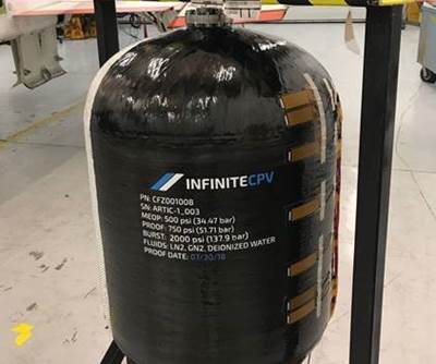
The first commercial Type V composite pressure vessel
Composites Technology Development's first commercial tank in the Type V category presages growth of filament winding in storage of compressed gases.
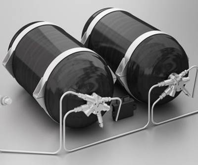
The evolution of vessels and tanks designed to hold liquids and gases under pressure has proceeded through four distinct stages: all-metal tanks (Type I), metal hoop-wrapped composite tanks (Type II), metal-lined composite tanks (Type III) and plastic-lined composite tanks (Type IV). The fifth stage, an all-composite, linerless Type V tank has been the pressure vessel industry’s Holy Grail for years (see the “Tank types” sidebar at the end of this article or click on its title under "Editor's Picks," at top right). Recently, one company, Composites Technology Development Inc. (CTD, Lafayette, Colo.), successfully designed, tested and built such a tank for a real-world application.
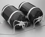
The company’s first commercial, all-composite, linerless pressure vessel was built in cooperation with the U.S. Air Force Research Laboratory (Wright-Patterson AFB, Ohio) and the University of Texas (Austin, Texas). It was installed on the student-built FASTRAC 1 (Formation Autonomy Spacecraft with Thrust, Relnav, Attitude and Crosslink) satellite, launched in November 2010. The 1.9L tank was approximately 6 inches (152 mm) in diameter, 7 to 8 inches (178 to 203 mm) in length and weighed only about 0.44 lb (0.2 kg). The tank was filament-wound with T700 carbon fiber supplied by Toray Composite Materials America, Inc. (Flower Mound, Texas) wet out with CTD’s proprietary KIBOKO toughened epoxy resin. It had an operational pressure of 200 psi, a proof pressure of 1,000 psi, with a burst pressure between 2,000 and 2,500 psi. The tank was used to store argon gas as a component of the satellite’s micro-discharge plasma thruster. The thruster superheats and channels the inert gas through a micro-channel nozzle, producing a micro-Newton level of thrust for orbital attitude adjustments.
Having proven its linerless pressure vessel’s mettle in space, CTD is looking to expand commercialization of the tank to more mainstream markets and applications. The company is in the process of qualifying a Type V tank for a commercial aircraft application. At the time this article went to press, CTD was building the first prototype tank for testing and had not decided whether the final version would be made of carbon or glass. Mike Tupper, CTD’s executive VP, says the goal is to have the tank qualified in the next 10 to 12 months and to make it available to the aircraft industry in the next two to three years.
CTD’s linerless tanks are expected to range from 15 to 20 percent lighter than their nearest Type IV cousins, a significant performance benefit in the aerospace/aircraft industry, which is sensitive to payload weight. A better weight-to-tank capacity ratio, however, is not the only advantage of a linerless pressure vessel, Tupper notes. Company studies indicate that after they are in full-scale production, linerless tanks will cost less to manufacture, most obviously because the costs of the liner material and liner fabrication will be eliminated. Less obvious is the fact that engineers also will have more flexibility during development to make design changes.
“Lined tanks are difficult and costly to make changes to once they are built,” says Tupper. He reports, for example, that CTD is working with an unmanned aerial vehicle (UAV) manufacturer that is interested in having a tank similar to the one used in the FASTRAC satellite. CTD built one prototype and has since supplied commercial tanks to the UAV manufacturer. The tanks will be used to hold fuel and will operate at 200 psi. Tupper says CTD was able to increase the volume of the tank by about 15 percent through a simple modification to the tooling. In a lined tank, the liner is the tool and, therefore, would need to be redesigned.
Additionally, liner-free, all-composite tanks can be made in conformal shapes, allowing tank designers to use the space in aircraft envelopes with constrained, nonuniform geometries. This attribute, Tupper believes, will speed market penetration in the aircraft industry after the company has qualified the first tank. “During the design of an aircraft, the tank design is often left until the end, and you have to fit it to the available envelope,” Tupper explains. “It is much easier to make a conformable tank with all-composite laminate than a metal tank or a composite tank with a metal liner.”
Type V technology
CTD’s hopes for mainstream, high-volume Type V applications rest with innovations on three major technological fronts: materials, design and tooling. The use of a single material to manufacture a tank meant developing a laminate system that could not only provide sufficient structural strength under pressure but — critically important — also form a barrier layer that is impermeable to gases, fuels and other substances. Tupper says its KIBOKO family of toughened resins, mostly based on epoxy, is the key to CTD’s development of Type V vessels.
“When you pressurize a tank, the pressure is applied to the vessel walls in all directions, so the resin has to stretch to absorb the strain and also provide structural support by bonding to the fibers,” says Tupper. He reports that tests conducted by the company have found that KIBOKO materials form microcracks at significantly higher strain levels, at both room and cryogenic temperatures, than do standard industry materials. Although the tanks for the FASTRAC satellite and the UAV are both wet wound, the same resin also is compatible with the vacuum-assisted resin transfer molding (VARTM) process. “There are certain applications where VARTM might be a more suitable way of making a low-void laminate,” says Tupper, “as long as you can be assured of getting a reasonable fiber volume fraction.” He reports that the company is currently leaning toward VARTM to manufacture the tank for commercial aircraft.
A single-material tank that meets requisite structural and barrier performance requirements is made possible by fine-tuning the design parameters, such as fiber angle, fiber volume and laminate thickness, to create what Tupper calls a “graded composite.” Although the laminate acts as both structure and barrier in all areas of the tank, engineers can adjust the design features to vary the functionality. They can, for example, emphasize the structural or barrier properties in particular locations within the tank wall rather than apply the change to the entire tank.
Further, vessels without discrete liners require a tooling substrate that must be removed after the vessel has been cured. CTD has worked with suppliers to develop several novel tooling techniques for molding composites with trapped shapes. Tupper says the tanks for both the FASTRAC satellite and the UAV are manufactured by winding filaments around an unconventional mandrel, which is chemically dissolved in a postprocessing step. He reports, however, that the method is suitable for tanks manufactured in small quantities but would not be cost-effective for large-scale production.
The company has worked on developing a new (pat. pend.) and more efficient method for molding trapped-shape composites, called Multiple Use Precision Extractable Tooling (MUPET). The process uses CTD’s open-cell, shape-memory TEMBO Foam, which is encased in a bladder. The tool is designed to have the desired shape of the tank. The foam is rigid enough at room temperature to enable the composite to be laid up on the foam tool, even using fiber placement and automated tape placement techniques. A composite laminate is manufactured around the mandrel using filament winding, VARTM or prepreg materials.
During cure, the bladder is pressurized to consolidate the composite. After the cure is complete, while the foam is still warm, a vacuum is applied to the foam and the volume of the tool is significantly reduced, which allows it to be extracted from the tank. After the tool is removed, the vacuum is released and the tool reportedly resumes the shape necessary to form the next tank. CTD can adapt the softening temperature of the tool to accommodate different cure cycles. The MUPET tool also can be used to create a well-consolidated composite when the layup is prepreg, without the use of an autoclave.
CTD has yet to decide which tooling methodology it will use to make tanks for commercial aircraft, but Tupper reports the company is investigating ways MUPET technology could be used to manufacture large composite tanks for NASA launch vehicles. A rocket typically has two metal tanks, one that carrries an oxidizer (usually oxygen) and another that carries fuel, such as hydrogen. “We’ve demonstrated, using our composite technology, that you can create a single tank with two compartments,” Tupper says, “so instead of having two tanks with a total of four ends, you have a more compact arrangement of one tank with two external ends and an internal bulkhead.”
The U.S. Department of Transportation’s regulations mandate lined tanks for compressed natural gas (CNG), so this particular high-volume market remains, for the time being, off limits for CTD’s linerless pressure-vessel technology. Nonetheless, Tupper believes that after the safety and reliability of linerless technology is demonstrated, its benefits could prompt regulators to amend this requirement. In the meantime, the company is finding growing interest and opportunities for its linerless tank technology in space, aerospace and light-rail specialty markets.
New materials will create lighter, larger CNG tanks
If steel and metal- or polymer-lined composite tanks remain the standard CNG storage vessels for now, there are several compelling reasons tank suppliers to the natural gas and transportation industries might want to revisit and improve current tank technology. First, the fuel tank on a CNG-powered vehicle is currently the single most expensive vehicle component. Second, because natural gas is domestically abundant, cheaper than gasoline and burns cleaner, it is increasingly viewed as a viable auto fuel alternative. CNG consumption in the U.S. has increased 145 percent in the past six years, according to the Consumer Energy Center (Sacramento, Calif.).
These realities prompted 3M Engineered Products and Solutions (St. Paul, Minn.) to announce recently that it will launch a complete portfolio of new Type IV CNG tanks that are 10 to 20 percent lighter — with 10 to 20 percent greater storage capacity at the same footprint, and with a lower cost — than the standard composite storage vessels (Type II through IV) currently on the market. 3M is collaborating with Chesapeake Energy Corp. (Oklahoma City, Okla.), which pledged an initial investment of $10 million for the project and committed to using the new tanks for its corporate fleet conversion to CNG. HyPerComp Engineering (Brigham City, Utah) is supplying design and certification services.
Rick Maveus, global business manager, 3M Advanced Composites, says the portfolio of tanks will provide 3M with “about 90 percent coverage,” of the CNG tank market for transportation. The first tank, with dimensions of 21.5 inches by 60 inches (54.6 cm by 152.4 cm), will be introduced in the fourth quarter of 2012. Maveus says 3M will subsequently launch one or two new tank geometries every month.
The tanks will be manufactured primarily from carbon fiber, as well as a combination of proprietary liner materials, barrier films and coatings, damage resistance films and — the key innovation and enabler in the tank technology — 3M’s nanoparticle-enhanced resin technology, 3M Matrix Resin for Pressure Vessels.
Tanks in the first phase of the launch will be manufactured by wet filament winding. Fibers will be wet out with the 3M resin via resin bath. The resin comprises amorphous and spherical nanosilica particles, approximately 100 nm in diameter, dispersed in an epoxy resin. “What is proprietary about our nanosilica-enhanced resin is that we are able to control the surface properties of the particles so that they disperse uniformly in the resin,” Maveus says.
Uniform dispersion, along with small nominal diameters, enables the particles to flow evenly between the fibers of the composite and achieve higher loadings, which, in turn, stiffens the resin and imparts improved mechanical properties to the composite. The nanoparticles are loaded into the composite matrix at levels of 40 to 50 percent, compared to loadings of 1 to 2 percent typically achieved with a carbon nanotube-infused laminating resin system. “The aspect ratio — surface to volume — of carbon nanotubes fundamentally limits loading,” Maveus notes. 3M reports that vessels made with the silica nanoparticle-enhanced resin show a 6 to 8 percent improvement in burst pressure, a 30 percent improvement in burst-pressure-after-impact and a 55 percent increase in fatigue life, compared to vessels made with conventional epoxy resins.
The higher modulus and fracture toughness afforded by the silica-filled epoxy/carbon fiber composite enables a tank design that weighs less but has greater capacity in the same footprint. In the U.S., service pressure for a CNG tank is 3,600 psi. Tom Hannum, business development manager at Hypercomp Engineering, says the firm was able to arrive at a proprietary design for the tank that achieves the same service pressure with less material. Hannum says the design strategy targets the most popular and widely used tank geometries on the market. The first tank will be certified to the American National Standards Institute’s revised compressed natural gas vehicle fuel container certification standard (NGV2, 2007) shortly before its release to the market.
Maveus notes that barrier, liner and film technologies will become increasingly important when looking at other opportunities. This will be especially true for those who develop pressure-vessel technologies for more exotic fuels, such as hydrogen, where the risk of permeation is no small matter. “No Type IV tank has been able to sufficiently address the permeation problem with hydrogen,” he points out, noting that 3M Advanced Composites intends to apply its tank technology to this application, down the road.
Offering its first tank in the Type IV category, GASTANK Sweden AB, a new subsidiary of HFC Sweden AB (Norrfjärden, Sweden), has opened for business with a focus on designing and manufacturing tanks and systems for CNG and compressed bio-gas for cars. Its first tank for commercial use is the 32L capacity Gastank, with a liner made of Akulon Fuel Lock, a polyamide 6,6 thermoplastic resin system supplied by DSM Engineering Plastics (Sittard, The Netherlands). DSM reports that tests of a tank molded from Akulon with a nominal 2-mm/0.079-inch wall thickness exhibited an evaporative emission rate 20 percent less than the U.S. Environmental Protection Agency’s limit for CNG tanks. The liner is overwound (via filament winding) with trademarked HiPer-tex high-performance glass fiber, supplied by 3B-the fiberglass co. (Battice, Belgium). GASTANK Sweden is billing the product as a “zero-permeation cylinder,” based on gas permeation tests conducted by Powertech Labs Inc. (Surrey, British Columbia, Canada). Tim Vorage, application development manager at DSM, contends that Akulon Fuel Lock not only demonstrates in tests a permeation factor “at least 150 times lower than high-density polyethylene (HDPE), it also significantly limits creep under extreme temperatures at the cylinder’s neck, thanks to a 50°C higher temperature resistance than HDPE.”
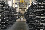
Another new entry in the Type IV segment, the GENIE, was introduced in March by Linde Gases, a division of Linde Group (Munich, Germany). The steel-lined tanks are strengthened with filament-wound SIGRAFIL C50 T024 EPY, a 24K carbon fiber supplied by SGL Carbon SE (Wiesbaden, Germany). The selected fiber grade has enhanced strength and stiffness and was developed specifically for high-performance applications, such as pressure vessel winding. Additionally, the tank exterior is encased in an HDPE jacket. The company reports that the GENIE is significantly lighter than its steel counterparts and — unlike most tanks, which are manufactured in a standard cylindrical shape with rounded ends — is ergonomically designed for stable stacking (see photo, ).
GENIE gas pressure vessels currently come in a range of pressures, including a 300 bar/4,350 psi version that has 30 percent more capacity than its standard 200 bar/2,900 psi all-steel counterparts. GENIE tanks come in three sizes suitable for different gases and mixtures, including argon, shielding gases, nitrogen, helium, carbon dioxide (CO2), refrigerants and liquid petroleum gas (LPG).
Related Content
Adhesives, material solutions promote end market versatility
CAMX 2023: Rudolph Bros. and Co. highlights its role as a prominent specialty chemical distributor and solutions provider with a display of high-performance adhesives, sealants, materials and more from well-known manufacturers.
Read MoreHenkel receives Airbus qualification for European aerospace manufacturing facility
The adhesive company’s Montornès, Spain, plant has been approved as a standard and raw materials supplier for various Airbus platforms, adding to its work in lightweighting, fuel efficiency and automation.
Read MoreResins, additives, adhesives and 3D printing solutions
CAMX 2023: Arkema’s broad portfolio of products for composites fabricators aim to enhance performance, durability and sustainability.
Read MorePro-Set named official materials supplier for New York Yacht Club American Magic
Competitive sailing team prepares for the 37th America’s Cup beginning in August 2024 with adhesives, resins and laminate testing services for its AC75 monohull construction.
Read MoreRead Next
Composites help take the waste out of wastewater
The role of composites for meeting California’s 21st century water needs.
Read MorePlastic Omnium confirms its position in CFRP hydrogen storage tanks
Contract for 350-bar bus tanks and certification for 700-bar passenger car tanks recognize developed technology and strategy for growing global hydrogen/fuel cell ecosystem.
Read MoreGraphene technology enables composite cryogenic pressure vessels
Infinite Composites incorporates Applied Graphene Materials’ graphene technology into two resin systems for cryogenic pressure vessels being considered for NASA missions.
Read More
