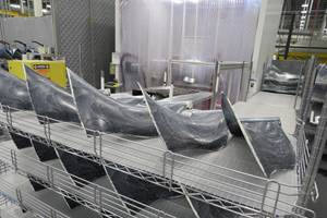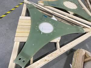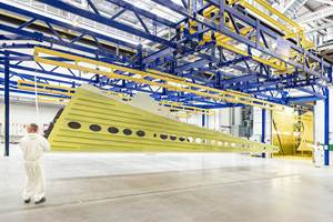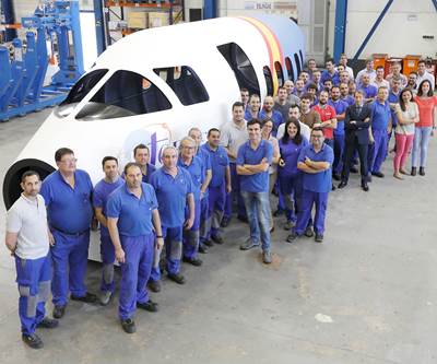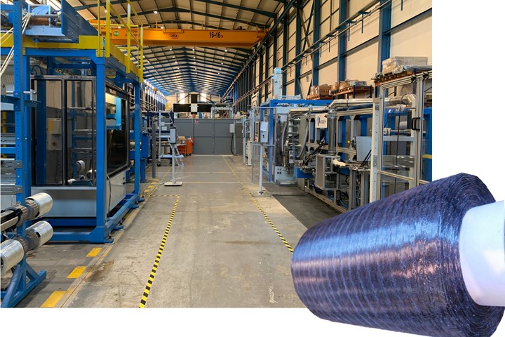
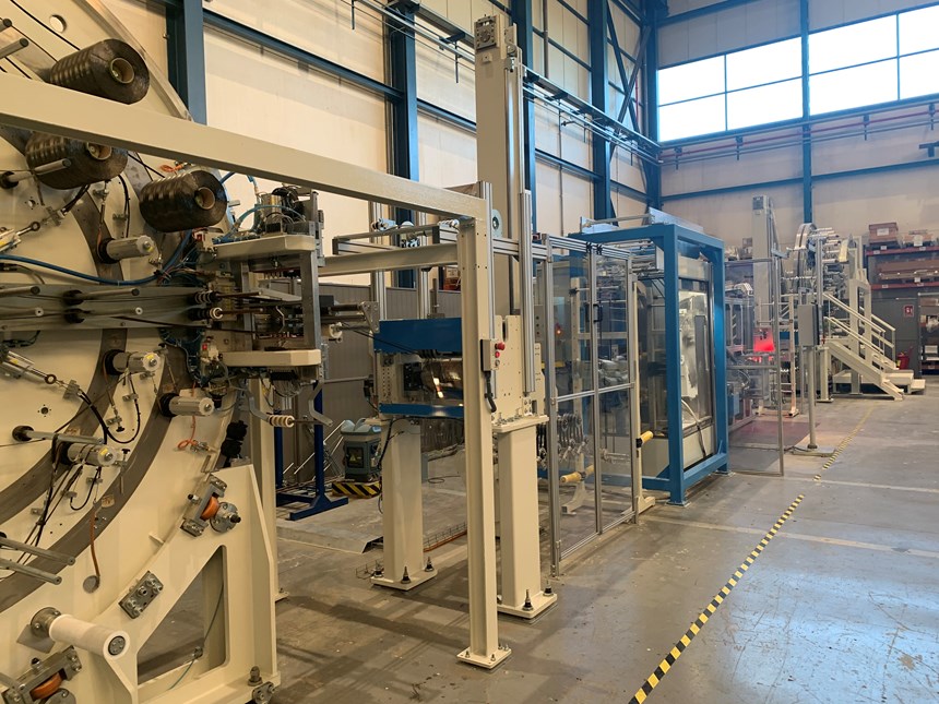
A leader in AFP technology, MTorres has combined this expertise with its long history in papermaking to develop a patented, novel dry fiber tape and high-speed production process — including a 0.5-inch-wide carbon fiber tape line (right) and a more versatile line for tapes up to 2 inches wide (inset) using glass, carbon or other fibers (left). The goal is to lower the cost of AFP composites to enable next-gen applications and open new markets. Photo Credit: MTorres
Improved cost, efficiency and sustainability are key for composites to enable the next generation of aircraft. One technology being developed to meet these goals is automated fiber placement (AFP) of dry fiber tape followed by liquid resin infusion or resin transfer molding (RTM) for out of autoclave (OOA) cure. CW has written about this development in several articles (see “Automated aerocomposites production: Liquid molding …”, “High-rate automated RTM line …” and “Infused wing sheds light on aerocomposites future”).
In CW’s 2018 article, “A complete paradigm shift in aircraft construction,” AFP equipment and composites automation specialist MTorres (Torres de Elorz, Spain) detailed its disruptive Torreswing composite fuselage and wing technology that eliminates conventional tooling and fasteners during automated fabrication of large, one-piece structures. Demonstrated in a business aircraft-sized fuselage, MTorres used premade composite rings and floors to form the structural skeleton/mandrel, which it then overwound using dry carbon fiber tape and AFP to create the layup for the outer skin. Skeleton and skin were then vacuum-bagged and converted into an integrated composite monocoque using resin infusion and oven cure (Fig. 1).
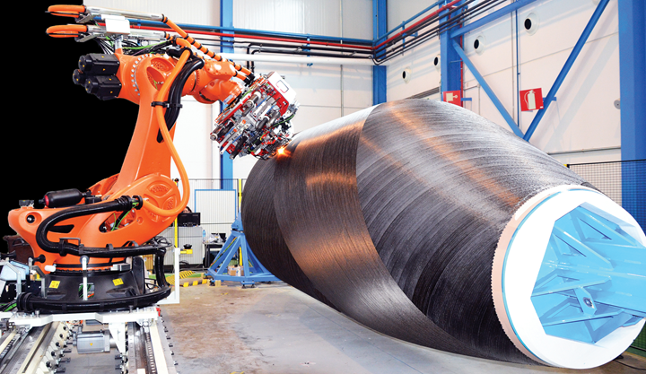
Fig. 1. Pioneering OOA aerostructures
Torreswing technology uses AFP, dry carbon fiber tape and resin infusion to create a business jet fuselage without autoclave, tooling or fasteners, cutting weight as well as tooling and labor cost. Photo Credit: MTorres
MTorres claimed this technology reduces weight, tooling and labor cost, but can also cut raw material cost by up to 50%. How? MTorres developed its own dry carbon fiber tape for the process. Notably, though the process was “born from our experience in wind blades,” says Iñigo Idareta, head of MTorres Special Projects, “it can accommodate prepreg, thermoplastic materials and other formats, as the customer wants."
In this article, CW walks through MTorres’ patented dry fiber tapes and automated, high-speed production lines. Optimized for AFP and high resin permeability, the tapes allow infusion of thicker structures, while the production lines can convert 50K carbon fiber tow or 4800 tex glass fiber rovings at rates five to 10 times faster than state-of-the-art production by current tape suppliers.
“Our founder, Manuel Torres, saw this technology approach as the future,” explains Idareta. “By using dry tape, the extra cost of prepregging and freezer storage is avoided, as is an autoclave. Our 44-year history in papermaking, including winding and splicing of materials, is now being transferred to fiber-reinforced composites. We have developed these new materials to enable infusion of affordable, large composite stuctures because it was not available in the market. These new lines also enable making small batches of new tape materials, something large suppliers have been unwilling to do.”
Origins outside of aerospace
This novel tape technology began more than 10 years ago in a program well outside the aerospace industry. “We were working with what is now Siemens Gamesa Renewable Energy, developing an automated manufacturing process for wind blades,” explains Idareta. “But we didn't have a dry glass fiber material in a format that we could use in AFP. At the same time, we also started to discover that the market wasn’t ready for such automation due to the high cost of the tape materials required. We found the same situation in automotive with carbon fiber. For both markets, we could see that fiber placement was important for reducing scrap compared to noncrimp fabrics (NCF) and nonwovens, but there weren’t any materials cost-efficient enough to make it viable.”
“We started first with glass fiber and a stitching process to bring together rovings into a 50-millimeter-wide format,” recalls Lucia Iniesta, MTorres lead composites engineer on the dry fiber tape project. “However, the productivity of the stitching process, at 2-4 meters/minute, was not high enough to achieve the low cost required. So, we started to think about higher productivity and came up with a number of ideas: replacing stitching with a high-temperature veil, electrostatic deposition of a low-temperature binder for AFP processability and a method to improve permeability, both in-plane and through-thickness, for faster and more reliable resin infusion.”
When the team put those ideas together, however, it was first for carbon fiber, resulting in a lab-scale pilot line for 0.5-inch-wide dry fiber tape. “This tape performed very well in our AFP equipment,” notes Idareta, “better than other commercially available dry fiber materials. But more importantly, it could achieve a much more efficient cost and still provide good performance in the final component properties. We then decided to develop a new line with more versatility, including options to use different fibers and different widths. We want a process that allows us to produce the materials that our customers could require.” The technology for the carbon tape was thus modified to produce glass fiber tapes and widths up to 2 inches.
Anatomy of a novel tape
To understand the tape production lines, it is helpful to first understand the tapes they produce. The right image in Fig. 2 shows a 0.5-inch-wide carbon fiber tape with a pattern of overlapping circles. These are formed by a melted high-temperature thermoplastic veil that coheres the tows into a tape while increasing in-plane permeability during resin infusion. These strands of thermoplastic filament can also be seen on the 2-inch-wide tape in Fig. 2. Both tapes are also coated with a low-temperature thermoplastic powder binder that allows rapid laydown and excellent forming of tapes during AFP. Slit-like perforations along the fiber axis of both tapes improve through-thickness permeability of the layup. Made by pushing the fibers aside, the slits neither cut nor distort the fibers, which would reduce their load-carrying capability and result in a knockdown of mechanical properties.
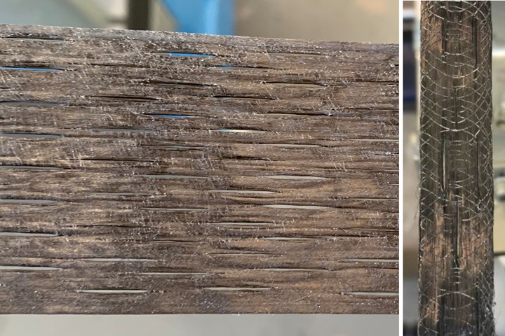
Fig. 2. Novel dry tape
MTorres’ patented new dry tape increases permeability in the z-direction via slits oriented in the fiber direction and in-plane via a high-temperature thermoplastic veil, seen as white circles on the 0.5-inch-wide tape (right) and faint white arcs on the 2-inch-wide tape (left). Photo Credit: MTorres
Novel production lines
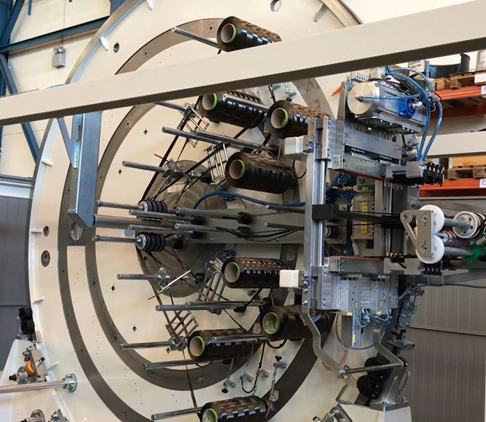
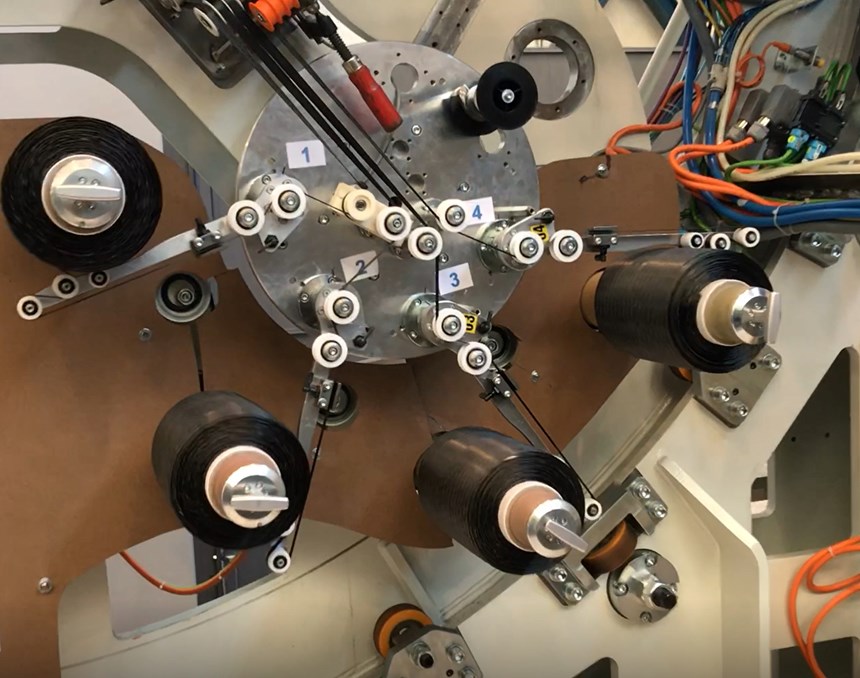
Tape production starts with multiple spools of either 50K carbon fiber tow or 4800 tex glass fiber roving (Step 1). “These are the main materials used so far,” says Iniesta, “but any other material and roving size available can be introduced in the process.” The tows/rovings are then conditioned to adjust their width (Step 2). A series of rollers that can be raised and lowered are manipulated to control tension and build a buffer in the tape line for switching out one set of input spools for another without stopping the line (not shown in manufacturing steps).
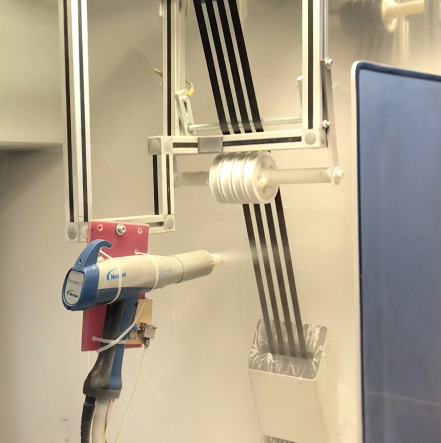
The next station applies a low-temperature binder with an electrostatic deposition gun (Step 3). “We heat and then cool to melt the powder binder and resolidify, stabilizing the tape,” explains Iniesta. “This will also provide adhesion between layers during AFP. To use AFP with infrared heating at a fast laydown rate you need a binder with low melt temperature. When we trialed the novel tape with this binder in our machines, we achieved a laydown speed of 60 meters/minute.”
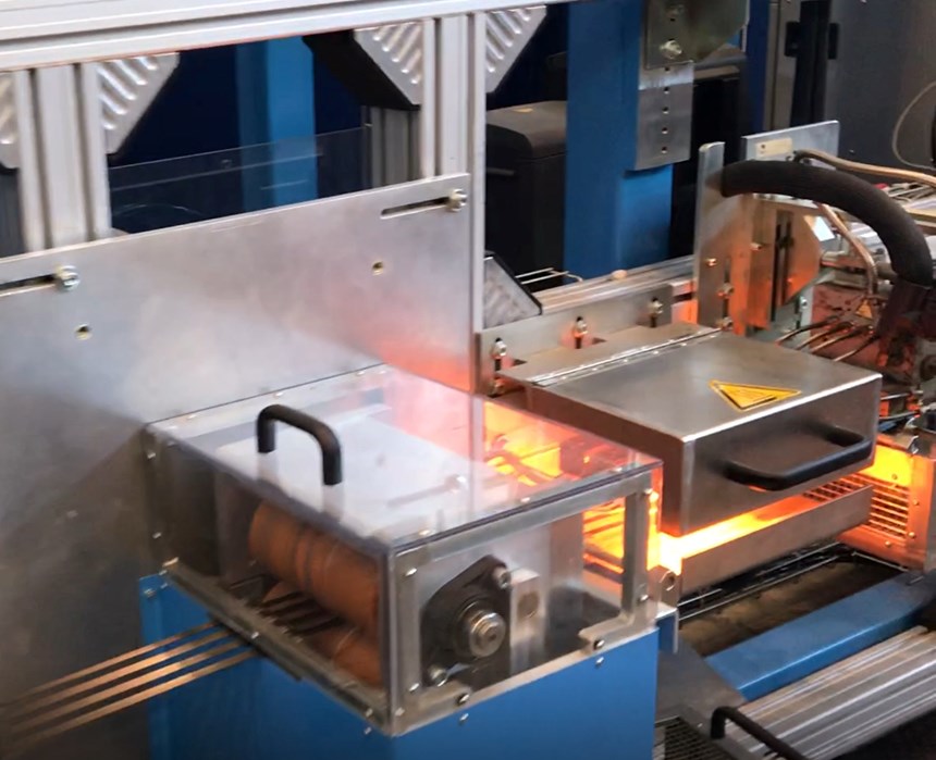
After the low-temperature binder is cooled, the high-temperature binder is applied (Step 4). “We melt thermoplastic pellets and blow this with hot air to create a fine mesh-like veil on one or both sides of the tape simultaneously at high velocity,” says Iniesta. “We control the diameter of the veil’s polyamide filament because it affects the in-plane permeability, as does the overall ratio of binders to fibers in the tape, which we maintain at a specific low percent.” The tape is heated using infrared (IR) lamps very close to the carbon fiber tape, which absorbs radiant energy very well. “It heats very quickly,” adds Iniesta, “to fuse the binder and give cohesion to the tape. The veil also stiffens the tape, which helps to keep its edge-width constant.”
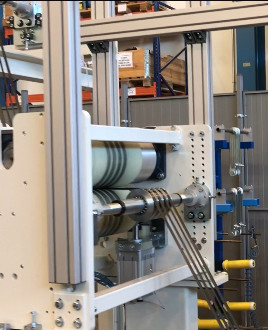
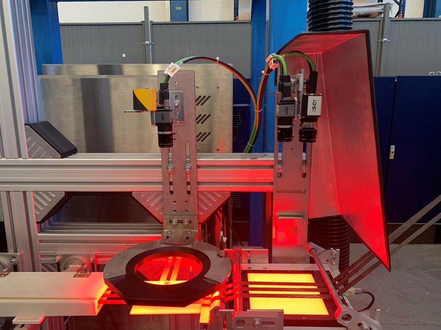
After the tape is once again cooled, it passes over spiked rollers, which create the slits for z-direction permeability. “We stabilize these so that they remain open even when we apply tension during AFP,” notes Idareta. The tape then passes through an automated inspection station. “The first light checks the tape width and application of veil, while the second measures the percent of light through the slits,” Iniesta explains. “We check these versus the tape specifications and when we see a deviation, we can adjust to maintain consistency and reduce variation.”
After inspection, there is again a series of vertically-actuated rollers before the tape is rewound onto bobbins for use in AFP machines. “We use the vertical actuation in the buffering rollers to reduce speed during bobbin changeout,” says Idareta. “The line speed is so high that you must have automated changeout when the bobbins are full. You never stop the line.” This is done, he notes, to reduce the capital and operating expenses for the material, especially the labor cost. “We try to reduce it to a minimum thanks to a much higher productivity. Our prototype line runs at 50 meters/minute with a maximum speed of 75 meters/minute and we expect 200 meters/minute for a fully industrial line.”
Manufacturing Steps
Glass vs. carbon fiber tapes
The production line for glass fiber tapes is similar but not identical. “The carbon fiber has thermal conductivity that is not the same with glass fiber,” explains Iniesta. “We use infrared to heat the carbon fiber, which conducts that heat to the high-temperature polyamide veil. But with glass fiber, that’s not possible. So, we changed the composition of the binder to enable heating the veil without thermal conductivity in the fiber. We also had to modify some parameters to achieve the same efficiency as with carbon fiber and also with good properties,” she adds. These lines can work with practically any glass fiber or carbon fiber in the market, including high-strength (HS), intermediate-modulus (IM) or high-modulus (HM) carbon fiber.
There are two pilot lines now running: a 0.5-inch-wide line for carbon fiber and a versatile line for up to 2-inch-wide tapes using glass, carbon or other fibers. “We have done some testing on other widths but those are the ones that we are working with the most and see as having the most interest from the market,” says Iniesta.
“Though we have the ability to make different areal weights,” says Idareta, “at this moment, we are producing 300 grams per square meter with 50K carbon fiber and 1,200 grams per square meter from multiple 4800 tex glass fibers in a 2-inch-wide tape. We also make a 2-inch-wide carbon fiber tape that is 0.52 millimeters thick at 517 grams per square meter.”
Slitting, tolerances and future development
One of the main ideas of these production lines is to avoid slitting. “This is a critical difference versus currently available materials and helps to reduce cost,” says Idareta. “Our tolerance is not quite as tight as with slit prepreg tape, but it’s more than enough to make good parts.” Iniesta says the team has tested its novel dry tape versus slit tape with tighter width tolerances in AFP parts, and it compares well. “The tolerance for our 0.5-inch-wide carbon tape is ±0.3 millimeters,” she notes. “This is good versus the market, but more important is to control the layup and we do this with tension control in our AFP machines. So, we don’t really need that tight of a tolerance for tape used in our machines, but we continue to improve it for the industry.”
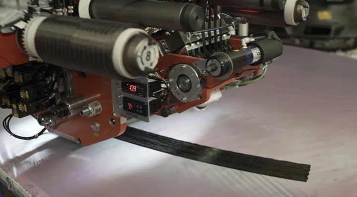
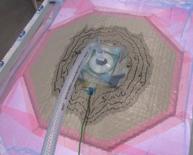
Fig. 3. Optimized for AFP and resin infusion
Tests of MTorres novel dry tape shows better steering versus prepreg tapes, enabling more complex geometries (top) as well as higher permeability during resin infusion (bottom) and better mechanical properties in finished composite structures. Photo Credit: MTorres
“We have tested these tapes with our AFP machines and they work well with hardly any modifications to the equipment,” says Idareta. “Also, we can get better steering with this dry fiber versus prepreg tapes, which enables more complex geometries.” The team has also evaluated the tapes in resin infusion, achieving good properties with aeropace-grade RTM6 (Hexcel, Stamford, Conn., U.S.) epoxy resin and with an industrial-grade epoxy from Huntsman Advanced Materials (The Woodlands, Texas, U.S.). Iniesta notes the 0.5-inch-wide, 300 grams per square meter, 0.3-millimeter-thick carbon fiber tape shows better mechanical properties — including interlaminar shear and compression strength — and processes better than off-the-shelf tape from existing suppliers.
“We’ve also made the same tape with carbon fiber commingled with polypropylene (PP), polyamide and PEI,” says Idareta. “This thermoplastic tape does not need slits for permeability. We have demonstrated carbon fiber/PP parts for automotive, achieving a 2-minute cycle time using hot press stamping, oil heating and a nickel mold with ceramic on the back to prevent heat loss. We also used a special PP filament to ensure no shrinkage.” Another interesting development is a new AFP head for 2-inch-wide, aerospace-grade dry carbon fiber tape that will be demonstrated in a prototype part being made with Airbus.
So what is MTorres’ endgame? “We could sell the equipment or license the technology,” says Idareta, “or directly become dry fiber tape suppliers. But our motivation is to grow composites. If we want to introduce carbon fiber into new markets, we must lower not only cost but also risk. At MTorres, we have the experience in fiber placement and infusion processes to cover the whole supply chain of technologies and requirements for parts manufacturing. In this way, we are training and helping future customers to make their components in the most efficient and least problematic way and to get the desired part performance.”
He notes that MTorres works together with its customer in their learning curves, “regardless of the composites offering. And we have imbued our knowledge of process into these new tape lines. This vertical integration from raw material to the final solution is allowing us to offer disruptive and customized solutions, unblocking opportunities even beyond the aeronautics industry, and we are already looking forward to the great reboot of the post- COVID-19 era.”
Related Content
Plant tour: Albany Engineered Composites, Rochester, N.H., U.S.
Efficient, high-quality, well-controlled composites manufacturing at volume is the mantra for this 3D weaving specialist.
Read MoreRTM, dry braided fabric enable faster, cost-effective manufacture for hydrokinetic turbine components
Switching from prepreg to RTM led to significant time and cost savings for the manufacture of fiberglass struts and complex carbon fiber composite foils that power ORPC’s RivGen systems.
Read MorePlant tour: Spirit AeroSystems, Belfast, Northern Ireland, U.K.
Purpose-built facility employs resin transfer infusion (RTI) and assembly technology to manufacture today’s composite A220 wings, and prepares for future new programs and production ramp-ups.
Read MoreIMDEA introduces digital twin for real-time analysis of composite materials production
Newly designed digital twin by IMDEA and Technical University of Madrid researchers enables manufacturers to see inside composite materials as they are being produced, facilitating early detection of faults.
Read MoreRead Next
A complete paradigm shift in aircraft construction
With its new Torreswing automated system for mold-free, fastener-free composite fuselage and wing construction, MTorres aims to revolutionize aerostructure.
Read MoreAll-recycled, needle-punched nonwoven CFRP slashes carbon footprint of Formula 2 seat
Dallara and Tenowo collaborate to produce a race-ready Formula 2 seat using recycled carbon fiber, reducing CO2 emissions by 97.5% compared to virgin materials.
Read MorePlant tour: Daher Shap’in TechCenter and composites production plant, Saint-Aignan-de-Grandlieu, France
Co-located R&D and production advance OOA thermosets, thermoplastics, welding, recycling and digital technologies for faster processing and certification of lighter, more sustainable composites.
Read More






.jpg;maxWidth=300;quality=90)
