Tabbing composite test specimens: The how
The when and why of tabbing composite test specimens were the subjects of my previous column (see “Tabbng composite test specimens: When and why," under "Editor's Picks," at right), which included a discussion of tabbing materials, tab thickness and taper angle, and adhesive selection.
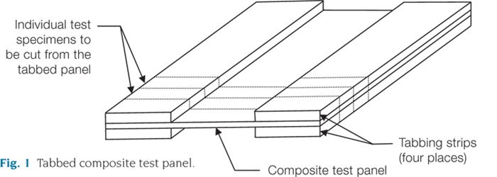
The when and why of tabbing composite test specimens were the subjects of my previous column (see “Tabbng composite test specimens: When and why," under "Editor's Picks," at right), which included a discussion of tabbing materials, tab thickness and taper angle, and adhesive selection. This article describes the how. I must emphasize that there is no one right way, so I will discuss several approaches. Without a doubt, some approaches will have more appeal than others to individual readers. However, each approach meets our objective: to adhesively bond four strips of tabbing material to a panel of composite material from which individual test specimens can be cut (see Fig. 1).
Perhaps the simplest approach is to apply adhesive to each of the four tabbing strips and then position them on a composite plate that has been marked to indicate the desired gage length. Masking tape can be used as a marker and will keep adhesive from getting onto the panel’s gage section. It also can be used to hold the tabbing strips in place during adhesive cure. Inexpensive and readily available, masking tape is often used, but it can be difficult to remove when the adhesive is cured at an elevated temperature. In that case, a more thermally stable tape might be a better choice.
As discussed last time, the adhesive can be paste or film. When paste adhesive is used, it can be applied to the tabbing strips and the composite plate. However, excessive application should be avoided to minimize cleanup. The use of a film adhesive minimizes the risk of excessive use and cleanup. But both adhesive types, in the uncured state, make it easy for the mating parts to slip out of alignment. Therefore, keeping the multiple pieces accurately positioned while the tape is applied can be a challenge. But with a little practice, it can be done.
Tab alignment is made easier by using two spacer plates, typically made of metal and similar in thickness to the tabbing strips. The plates’ length should equal the specimen gage length, but they must be wider than the composite panel so they can be bolted together at each end with the panel sandwiched between them. The spacer plates maintain the desired gage length when the tabbing strips are indexed against them. Tabbing strips then can be taped to the spacer plates, and to each other, to better prevent slippage during adhesive cure. Postcure cleanup is easier because the tape does not contact the composite panel.
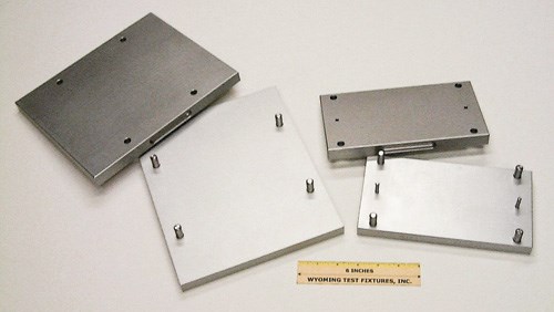
The easiest approach is to use a self-contained tab-bonding fixture (two examples are shown in Fig. 2). The fixture’s base plate is fitted with pins, against which the tabbing strips are indexed to establish the specimen gage length. That is, the pins serve the same purpose as the spacer plates of the previous approach. A tensile specimen tabbing fixture is shown on the left in Fig. 2. The top pins are spaced apart from the bottom pins to establish the desired specimen gage length. The right side of Fig. 2 shows a tabbing fixture for a Modified D 695 Compression specimen. Because this specimen has a very short (4.78 mm/0.188 inch) gage length, the fixture features two centered pins of this diameter (the smaller pins in the figure), and the tabbing strips for both ends of the specimen are indexed against them.
No matter which fixture is used, adhesive is applied to two of the tabbing strips, and then each is placed, adhesive side up, on the base plate and indexed to the appropriate set of pins. Then the composite panel is added and indexed against either the left or right pair of pins. Note that the tabbing strips must be wide enough to engage the indexing pins, and the composite panel must be narrow enough to fit between the left and right pins. Then adhesive is applied to the two remaining tabbing strips, and they are placed on the composite panel against the indexing pins. Finally, the fixture’s cover plate, with hole locations that match the pins in the base plate, is lowered into position to complete the assembly.
Fixture plates are typically aluminum. Its high thermal conductivity ensures efficient heat transfer during elevated-temperature curing. However, for adhesives that have very high cure temperatures, it might be desirable to use a material that exhibits greater strength and stiffness at high temperatures, such as stainless steel.
Regardless of the fabrication method, the bonding surfaces of both the composite panel and the tabbing strips must be adequately prepared prior to applying the adhesive. The goal is twofold: (1) remove all surface contaminants, such as mold waxes, release agents, greases and oils; and (2) roughen the surface to enhance mechanical bonding. On the panel, this is achieved by removing some of the plate’s thin, resin-rich surface by either light hand sanding or grit blasting. The latter is preferred when such equipment is available because sanding, if the panel has any surface irregularities, will remove more material at the high points, potentially damaging the underlying fibers. However, excessive grit blasting also can damage fibers. The surfaces then can be washed in water to remove debris, dried and then wiped with acetone, alcohol or similar solvent.
If tapered tabs are used, the taper can be achieved in several ways. The simplest approach is to use a belt sander with the tabbing strip resting on a tapered block of the desired angle. A conventional router also can be used. To increase speed and accuracy, a milling machine or surface grinder can be used, with the tabbing strip held at the correct angle by a clamping jig.
Another issue is control of the bondline thickness (typically 0.5 to 1.2 mm or 0.020 to 0.050 inch). Film adhesives are not problematic because the film is already a uniform thickness and typically has a woven glass carrier cloth embedded in it, which maintains the thickness during cure. For paste adhesives, the thickness can be controlled by placing a few glass beads or a wire of the appropriate diameter onto the adhesive at each end of the tabbing strip to act as a stop.
Compaction during cure can be achieved using weights, a vacuum bag, a press (with heated platens, if required) or an autoclave.1
Reference
1D.O. Adams and D.F. Adams, “Tabbing Guide for Composite Test Specimens,” Federal Aviation Administration Report No. DOT/FAA/AR-02/106, October 2002, online at http://www.tc.faa.gov/its/worldpac/techrpt/ar02-106.pdf.
Related Content
Numerical tool with mean stress correction demonstrated for fatigue life estimation of thermoplastic composites
To aid design of fatigue-resistant structures, Econ Engineering has developed an algorithm to evaluate ply-based cyclic stiffness degradation combined with an FE failure check, validated for a CF/PAEK pressure vessel.
Read MoreComposite test methods (and specifications) for fiber-reinforced concrete structures
While initially focused on transitioning existing standards published by the American Concrete Institute, the relatively new ASTM Subcommittee D30.10 is developing new standardized test methods and material specifications for FRP composites.
Read MoreNotched testing of sandwich composites: The sandwich open-hole flexure test
A second new test method has been standardized by ASTM for determining notch sensitivity of sandwich composites.
Read MoreMulti-scale 3D CT imaging enables digital twinning, high-fidelity simulation of composite structures
Computed tomography (CT) provides highly accurate 3D analysis of internal microstructure, performance simulation of carbon fiber/PEEK satellite strut.
Read MoreRead Next
Tabbing composite test specimens: When and why
Dr. Don Adams (Wyoming Test Fixtures Inc., Salt Lake City, Utah) discusses when and why test specimens must be protected by tabs.
Read MoreAll-recycled, needle-punched nonwoven CFRP slashes carbon footprint of Formula 2 seat
Dallara and Tenowo collaborate to produce a race-ready Formula 2 seat using recycled carbon fiber, reducing CO2 emissions by 97.5% compared to virgin materials.
Read MorePlant tour: Daher Shap’in TechCenter and composites production plant, Saint-Aignan-de-Grandlieu, France
Co-located R&D and production advance OOA thermosets, thermoplastics, welding, recycling and digital technologies for faster processing and certification of lighter, more sustainable composites.
Read More
