Testing Tech: Adhesion testing of sandwich panels
In my three preceding columns, I discussed the testing of sandwich panels as unit structures. This included flexural and shear testing of beams and panels. However, such tests — and hardware components that are designed accordingly — will not produce the desired results unless the adhesives that hold these panels
In my three preceding columns, I discussed the testing of sandwich panels as unit structures. This included flexural and shear testing of beams and panels. However, such tests — and hardware components that are designed accordingly — will not produce the desired results unless the adhesives that hold these panels together are adequate.
There are test methods for characterizing adhesives in bulk forms and as thin films between two arbitrary adherends, but none of these methods directly simulate the conditions in a sandwich panel, specifically the bonding between the actual core material — typically honeycomb or foam — and the facesheets. Thus, it is desirable to use test methods that directly evaluate the adhesive in situ.
Peel tests are the most popular and have been for many years. As the name implies, a facesheet is literally peeled off the core material of an actual sandwich panel. Of these tests, the so-called Climbing Drum Peel test is most used. It was standardized in 1960 as ASTM D 1781, “Climbing Drum Peel Test for Adhesives” by the American Society for Testing and Materials, now known as ASTM International (W. Conshohocken, Pa.) Note that this was during the same time (the second half of the 1950s) that all of the previously discussed sandwich panel tests were standardized. This test method has remained essentially unchanged.
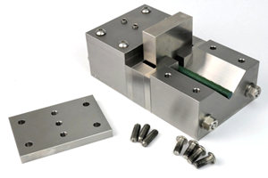
An actual test fixture is shown in Fig. 1, while the principle of operation is sketched in Fig. 2. The concept is essentially the same as that used to open an old-style can of sardines or canned meat. In those cases, a strip of metal is peeled off by winding it onto a key provided with the container. In the sandwich panel test, the facesheet corresponds to the metal strip, and the drum corresponds to the key. That is, the facesheet is literally wound onto the drum as the drum climbs up the facesheet under the applied axial tensile loading. Because only axial tensile loading is required, it is a relatively simple test to perform.
The ASTM version of the fixture features the very convenient cam-type grips shown in Fig. 1. An alternate standard, MIL-STD-401, which is seldom used today, uses simple bolt-on clamps. This MIL-STD was first introduced in 1956, even earlier than the ASTM version. Other than the clamping method, however, the two standards are essentially the same.
The sandwich panel test specimen can be as wide as 76 mm/3 inches, and the facesheet that will be peeled must be flexible enough to wrap around a 102-mm/4-inch diameter cylinder (the drum). A typical specimen is at least 305 mm/12 inches long (and thus approximately equal to one wrap around the drum after 25 mm/1 inch of core and opposite facesheet is cut away at each end of the specimen during specimen preparation for gripping purposes). While the thicknesses of the facesheets and the core are somewhat arbitrary, values on the order of 0.5 mm/0.02 inch and 13 mm/0.5 inch, respectively, are typical. Note, however, that the core and the opposite facesheet that will remain must be stiff enough to resist bending during the test, which limits how thin this assembly can be. For typical sandwich panels, with thicknesses in line with those noted above, this is not a problem.
The ASTM D 1781 Climbing Drum Peel test method also can be used to test the adhesive peel strength between two adhesively bonded solid sheets. In this case, the sheet from which the other is being peeled must be sufficiently stiff to remain straight. Often this is not the case. Thus, a 45-mm/1.75-inch-wide steel backing plate is provided with the ASTM fixture (center left in Fig. 1) to which this adherend can be mechanically fastened to keep it from bending while a 25-mm/1-inch wide strip of the other adherend is peeled from it.
Although a backing plate is provided with the ASTM D 1781 fixture, I suspect that it is seldom used. Rather, another standard test method, ASTM D 3167, “Floating Roller Peel Resistance of Adhesives,” is commonly used to peel two solid sheets apart. This test did not become an ASTM standard until 1973, but its method was developed earlier by Bell Aircraft and, at that time, was referred to as the Bell Peel test method. Although it is denoted by the phrase “floating roller peel” in the title of the ASTM standard, this method is more commonly called the Roller Drum Peel test, and is even referenced by that name within the ASTM standard. Two views of an actual ASTM D 3167 fixture are shown in Fig. 3. The principle of operation is shown in Fig. 4. Although a 25-mm/1 inch wide strip of adherend is peeled in ASTM D 3167, just as is done in ASTM D 1781, the former differs from the latter in one important respect: the diameter of the roller drum is only 25 mm/1 inch, significantly smaller than the 102mm/4-inch climbing drum, resulting in a much smaller peel angle. But the results of peel tests in general tend to be used as qualitative (comparative) rather than quantitative information. Thus, results from the two different tests normally should not be compared.
While there are a number of other solid laminate peel test fixtures and modifications, none are used as commonly as the two discussed above. Often these are referred to as 90° Peel test methods, an example of which is shown in Fig. 5. In this case, the stiffer sheet is supported by rollers so that it can move laterally as the more flexible sheet is peeled off. Because the use of sandwich panel composite structures is steadily increasing, it is probable that additional adhesive bond test methods will be developed. However, the two emphasized here have been in existence for many years. Their continued use indicates that they have stood the test of time — the most valuable test of all.
Related Content
Crashworthiness testing of composites: A building block approach, Part 1
Determining the crashworthiness of composite structures requires several levels of testing and analysis, starting with coupon-level crush testing.
Read MorePhotothermal tomography for locating, quantifying defects in composites
Years of infrared testing development result in thermography technology that is no longer just qualitative, but can define defect size and depth, making additional UT scans obsolete.
Read MoreMulti-scale 3D CT imaging enables digital twinning, high-fidelity simulation of composite structures
Computed tomography (CT) provides highly accurate 3D analysis of internal microstructure, performance simulation of carbon fiber/PEEK satellite strut.
Read MoreComposite test methods (and specifications) for fiber-reinforced concrete structures
While initially focused on transitioning existing standards published by the American Concrete Institute, the relatively new ASTM Subcommittee D30.10 is developing new standardized test methods and material specifications for FRP composites.
Read MoreRead Next
“Structured air” TPS safeguards composite structures
Powered by an 85% air/15% pure polyimide aerogel, Blueshift’s novel material system protects structures during transient thermal events from -200°C to beyond 2400°C for rockets, battery boxes and more.
Read MoreAll-recycled, needle-punched nonwoven CFRP slashes carbon footprint of Formula 2 seat
Dallara and Tenowo collaborate to produce a race-ready Formula 2 seat using recycled carbon fiber, reducing CO2 emissions by 97.5% compared to virgin materials.
Read MoreVIDEO: High-volume processing for fiberglass components
Cannon Ergos, a company specializing in high-ton presses and equipment for composites fabrication and plastics processing, displayed automotive and industrial components at CAMX 2024.
Read More


.jpg;maxWidth=300;quality=90)


