Upsizing blade test regimes
As composite rotor blade size grows, research groups act to meet the urgent need for physical testing facilities with large-blade capacity.
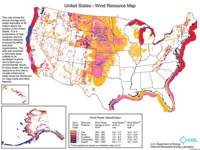
A great deal of research activity is currently focused on wind energy around the world. This has led to the creation of new academic research institutes and extensions of past research efforts. Examples of the former include the Wind Energy Research Center (WERC) at the University of Wyoming (Laramie, Wyo.) established in 2008. Center director, Jonathan Naughton, has highlighted the role the Center is expected to play in the development of Wyoming’s wind resources, which include 50 percent of the Class 6 and 7 areas in the continental U.S. The Center’s work seeks greater understanding of the wind resource and working to improve wind turbine technology, to benefit Wyoming’s growing wind energy industry. Examples of the latter include the European Union’s ongoing UpWind research program, which builds on the earlier OPTIMAT program. UpWind researchers are considering all aspects of wind energy development, including characterization of static and fatigue properties of composite materials used to fabricate wind turbine blades.
As previous CT articles testify, blade design is rapidly changing (see articles listed under “Editor's Picks," at right). Blades are getting longer, and in the process, heavier. In fact, blade size has changed so rapidly in the past few years that designers and manufacturers are having trouble finding testing facilities with the equipment and space to perform the necessary physical testing. This lack has prompted remedial measures, both in Europe and North America.
The limits of current blade testing
Wind turbine size is a factor that directly determines wind turbine energy generating capacity and cost efficiency. It also has a direct impact on rotor blade design. Larger turbines with longer blades have more swept area, that is, they capture a greater volume of available moving air and, therefore, harvest more wind energy. Additionally, their taller towers better position the rotors to capture wind at greater speeds than the wind speeds available closer to the ground. In fact, the cost of generated kilowatt hours (kWh) drops exponentially with increased swept area. This is an important element in the economics of wind energy, because subsidies and tax allowances, which can’t be depended on forever, currently compensate for any imbalance between the cost of wind-generated electricity and the cost of electric power produced by coal-fired and natural gas-fired power plants. There is a big push, therefore, to increase turbine swept area. The resulting increase in rotor blade length is outpacing the ability of researchers to produce and test new blade designs. The logjam, however, involves neither limitations in design nor lack of production capability. Researchers face no insurmountable barriers to conceiving or building longer blades. But once a blade is built, the means to test it are more scarce as blade length increases.
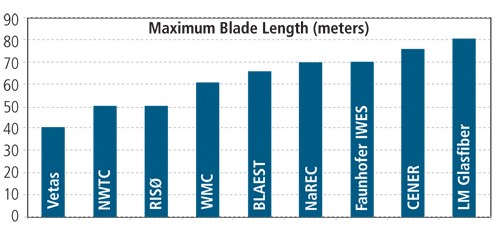
There are few places in the world now capable of testing blades longer than 70m/229 ft. Wind turbine blade manufacturer LM Glasfiber (Kolding, Denmark) claims the ability to test blades up to 80m/262 ft in-house, and has tested product that is 61.5m/203 ft long. The Centro Nacional de Energias Renovables (CENER) in Sarriguren, Navarra, Spain claims two test beds for blades up to 85m/279 ft long. Locations now capable of testing 70m/229 ft blades are Fraunhofer IWES (Bremerhaven, Germany), and in the U.K., the New and Renewable Energy Centre (NaREC, Blyth, Northumberland). Finally, the Blade Test Centre A/S (BLAEST, Aalborg, Denmark) currently can test blades as long as 65m/213 ft.
Many of these test facilities are now expanding. BLAEST’s managing director Carsten Skamris says the Aalborg facility will be able to handle 85m/279-ft blades by the end of this year, although he notes that most manufacturers are currently interested in well-instrumented tests up to 70m/229 ft. NaREC announced in December 2009 that it will build a £15 million ($24.3 Million USD) facility for testing offshore turbine blades up to 100m/328 ft in length. Similarly, Fraunhofer IWES has broken ground on a new facility that will go up to 90m/295 ft. Those involved in wind blade research in Europe are thus likely to have some testing facilities with large-blade capabilities available as blade designs increase beyond 70m/229 ft.
Augmenting U.S. testing capabilities
In the U.S., however, the National Wind Technology Center (NWTC) located at the National Renewable Energy Laboratory (NREL, Golden, Colo.) currently provides testing up to 50m/164 ft. As early as May 2006, NWTC personnel began making a case for building a blade test facility capable of handling longer blades in North America. An NWTC report issued at that time concluded the rapid growth in wind turbine blade lengths was outstripping NWTC’s testing capability. As a result, the North American wind industry was practically limited to blade lengths of 50m/164 ft, NWTC’s current testing limit. NWTC further contended that the alternative — sending blades to European facilities that are prepared to test longer blades — was not only logistically inconvenient, but also posed intellectual property, scheduling and cost concerns. (The report summarized test capabilities at various European facilities, as shown in Fig. 1. The blade lengths shown are somewhat arbitrary because maximum lengths depend on the selected test regime). The tremendous potential of offshore wind energy in the U.S. (the Great Lakes and the Northeastern Coast offer prime possibilities) was cited by NWTC as a driver that would demand blades, in future, that could range from 70 to 100m (229 to 328 ft) long.
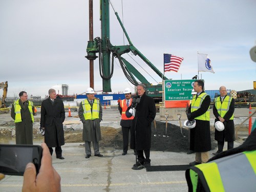
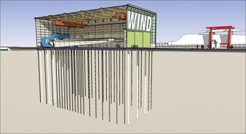
One result of this report was that NREL announced in 2007 that it would negotiate Cooperative Research and Development Agreements (CRADAs) aimed at establishing blade-testing sites in Texas and Massachusetts. In Texas, the University of Houston represented the Lone Star Wind Alliance, a public/private partnership that seeks to establish a Texas-NREL Large Blade Research and Test Facility (LBR&TF) in Ingleside. This facility is still on the drawing board. Closer to realization is the Wind Technology Testing Center (WTTC) in Boston, Mass. The WTTC is a $40 million project, with $13.2 million in funding coming from the Commonwealth of Massachusetts’ Renewable Energy Trust, $2 million from the NREL CRADA, and a recent $25 million stimulus grant from the U.S. Department of Energy (DoE). The groundbreaking took place Dec. 1, 2009 (see Fig. 2).
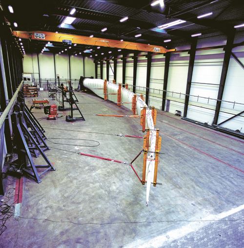
The WTTC test facility is expected to bring U.S. testing capacity up to par with that available in Europe. It reportedly will be capable of testing blades up to 90m/295 ft long in a fully enclosed space. The facility will require a very substantial subsurface structure to react the target loads applied to the blade during testing (see Fig. 3).
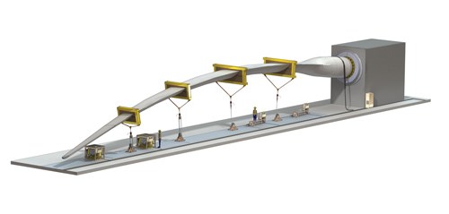
According to Rahul Yarala, WTTC executive director, the new facility will accommodate a 33m/108-ft blade tip deflection — enough room to facilitate destructive testing of blades sized for today’s huge offshore wind turbines. He also notes that the WTTC “will have a state-of-the-art winch system consisting of mixed hydraulic and electric winches vs. the typical electric motor winches at other facilities.” This will provide for greater versatility during static blade tests (Fig. 4). The International Electrotechnical Commission technical standard that governs full-scale structural testing of rotor blades (IEC/TS 61400-23) requires that IEC-certified facilities also perform dynamic testing (Fig. 5). The WTTC will be able to perform dual-axis resonant fatigue tests (oscillating the blade at its natural frequency), using methods and hydraulic hardware developed by NREL and MTS Systems Corp. (Eden Prairie, Minn.).
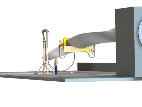
Jason Cotrell, one of the authors of the 2006 NREL report, notes several big advantages of the fatigue testing system planned for the WTTC. The technology will be able to scale well with increasing blade size. The system requires substantially less test energy than competing systems, thereby reducing test costs. Further, the system likely will be better able to test flap-twist-coupled blade designs. The WTTC system will use hydraulic oscillators, i.e., exciters acting as resonating masses, which will be mounted to the blade as shown in Fig. 5. Single or multiple oscillator setups can be used as needed to most efficiently excite the blade. And the test can be set up to fatigue the blade in the flap-wise and edge-wise directions simultaneously. This dual-axis testing is more representative of actual service, where wind load causes flap-wise deflections and gravity causes edgewise deflections.
Other methods of exciting blades during fatigue testing include using hydraulic cylinders to impose loads normal to the blade surface or using eccentric, rotating mass exciters mounted on the blade. Arguments can be made for and against each method. Nathan Post of Fraunhofer IWES notes that exciting the blade with a hydraulic cylinder mounted to the floor and mid-blade region adds little weight to the blade surface, but complicates control and uses more energy. At BLAEST, the rotating eccentric mass method has been used effectively, but it places a lot of weight on the blade and is not well suited to dual-axis testing. Biaxial testing is a key issue: As blades get longer, their natural resonant frequency decreases. This decrease makes it more difficult to generate the requisite 5 million cycles in both the edge-wise and flap-wise directions needed to simulate a 20-year service life. LM Glasfiber notes fatigue testing takes 3.5 months for a 37.3m/122 ft blade but can take an entire year for a 61.5m/202 ft blade. The ability to oscillate the blade in both directions simultaneously also can cut test times and costs by half.
Yarala confirms the WTTC will be operational in the first quarter of 2011, and that several established wind turbine manufacturers have inquired about test slots for blades, mostly in the 50m/164 ft range. Within three years of commissioning, he expects, the WTTC will be operating at or above 70 percent capacity and the Center will be fully self-supporting. In the longer term, the WTTC might be open to testing other large composite structures, such as turbine towers and bridge components. Sources in other large-blade testing facilities support the view that there will be ample demand to keep all the facilities busy, due to blade development for offshore turbines and the need to get designs promptly certified.
Implications for composites usage
While blade-testing personnel hesitate to make predictions about how their work is likely to impact blade designs and the market for composites, there is general agreement on several points:
- Larger blades will require increased use of more advanced materials, including carbon fiber, S-Glass and better bonding and core materials.
- Aerospace methods (used, for example, to join multiple blade segments) will be adapted into the wind industry, but gradually, due to this industry’s greater cost sensitivity.
- The offshore wind market is likely to live up to expectations, but may take somewhat more time to develop than currently projected.
- There will be an emphasis on developing flap-twist-coupled blade designs.
- Blade tests will become more sophisticated. More data acquisition will result in better characterization of blade performance as longer blades are developed, thus aiding blade designers.
These are exciting times for the wind industry. The DoE has set a goal of generating 20 percent of U.S. electricity from wind in 2030, which will require as many as 18,000 new offshore turbines. The WTTC and facilities like it are absolutely essential infrastructure if blade designers are to have the data they need to optimize blades longer than 50m/164 ft and realize the full market potential of offshore wind. The rapid increase in large-blade test facilities is a sign of the wind energy industry’s maturity.
Related Content
Aurora reveals latest SPRINT X-Plane design concept
An Aurora and Boeing team advances its high-speed, vertical lift concept to the preliminary design phase, which features three lift fans, a more refined composite exterior and an uncrewed cockpit.
Read MorePlant tour: BeSpline/Addcomp, Sherbrooke, QC, Canada
Composites automation specialist increases access to next-gen technologies, including novel AFP systems and unique 3D parts using adaptive molds.
Read MoreAutomated robotic NDT enhances capabilities for composites
Kineco Kaman Composites India uses a bespoke Fill Accubot ultrasonic testing system to boost inspection efficiency and productivity.
Read MoreComposite sidewall cover expands options for fire-safe rail components
R&D project by CG Rail explores use of carbon fiber-reinforced thermoplastics and recycled manufacturing scrap to meet fire safety, weight and volume targets.
Read MoreRead Next
Offshore wind: How big will blades get?
Explosive growth in offshore wind farms will push the limits of blade engineering as manufacturers pursue massive designs that will harvest more megawatts.
Read MoreWind turbine blades: Big and getting bigger
Two decades of technical and market development has made this once marginal application a global giant and one of the world’s largest markets for composites.
Read MoreAll-recycled, needle-punched nonwoven CFRP slashes carbon footprint of Formula 2 seat
Dallara and Tenowo collaborate to produce a race-ready Formula 2 seat using recycled carbon fiber, reducing CO2 emissions by 97.5% compared to virgin materials.
Read More



.jpg;maxWidth=300;quality=90)


