Share
Fig. 1. Both the permanent pattern and the layup mold in these images have flanges with generous radii outside of the part area, providing increased stiffness to the laminate and protection from edge impact. Photo Credit (above and in landscape image): Ascent Aerospace
The biggest complaint I get about composite versus metal molds is that they tend to leak over time. This is especially true when making low-temperature cure, high-temperature service laminated tooling. Sometimes they leak immediately when tested for first article compliance, causing the fabricator to desperately try to seal the leaks and (temporarily) fix the problem to save their own investment, or worse, deliver it on time to an unsuspecting customer. Regardless, fixing leaks after fabrication is undesirable, and over time scrapped parts and repeated repairs can prove costly.
What can be done upfront to ensure that molded composite tools do not leak in service? To answer this question, we need to understand what factors contribute to leaking tools in the first place. The following are some important points to consider.
Tool design
Adding flanges with large radii around the periphery of the tool can minimize the potential for edge impact damage during fabrication, demolding and in-service. The bonus to this approach is increased stiffness in the tool laminate itself, allowing for minimal support structure (Fig. 1). Consideration for flanges and other molded features occur at the model or pattern design, enabling layup of these features along with the tool laminate.
Material selection and process methodology
Prepreg materials and processes are desirable for best results. It is far more difficult to build wet layup (or infused) tools with reasonable control of the resin content and the ability to provide intermittent compaction steps (debulks) to avoid bridging in the corners during layup. It can be done, but at higher risk for leaks in production.
While often deployed as a time saver, the use of bulk fabrics in the laminate construction can be detrimental over time, as they often require extra resin to fill the intersections between yarns and adjacent layers. They are also more prone to bridging in corners or at overlaps, where resin will try to fill the low-pressure area created by the open space. The excess resin is problematic and will eventually microcrack, creating a leak path within the tool laminate. It is recommended that twill and/or harness satin (HS) fabrics with an areal weight of ≤500 gsm for carbon fiber or <700 gsm for glass fiber be used to minimize the problem. Note: HS fabrics require more scrutiny of warp face orientation to acquire true symmetry (Reference August 2022 article, “Doing the twist: A look at dimensional issues in high-temperature cured laminates”).
Multiple debulks are recommended for best results. The first ply should always be compacted so that it is tight to the model or pattern prior to the layup of subsequent plies. The number of plies between debulks depends on the mold configuration. The more complex the mold, the more debulks are required. A final overnight debulk is recommended prior to cure if time (and materials) allow, to draw off moisture, volatiles and provide laminate compaction prior to cure.
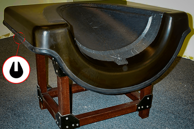
Fig. 2. This mold has an extruded rubber bulb bonded to the tool laminate to provide extra protection to the tool and the operator. Note the molded flanges and index features used in the mold design. Photo Credit: Abaris
Initial low-temperature cure
Highly reactive, low-temperature curing resins allow for good dimensional control between a model (or pattern) and the tool laminate by minimizing the thermal expansion factor during cure. Many prepreg tooling systems initially cure at ~65°C for a number of hours. Depending upon the system, where the temperature is measured and the heat transfer coefficient of the model, this may not be enough time or temperature to push the resin to maturity. It may appear to be cured, but it is not fully crosslinked. The vitrified resin at this stage is highly susceptible to fracture when impacted or flexed. Increasing the soak time at the initial process temperature or raising the temperature (after the initial cure) to ~80°C for a couple of hours can help push the crosslinks further towards maturity prior to demolding. Afterwards, a full post-cure above the intended service temperature is recommended before proceeding.
Microfracture of the matrix resin
If the matrix resin is damaged, it’s most likely to occur during the demolding process when wedges are used to remove the tool from the model or pattern. This is especially true with the exposed edge (pancake) tool design, where the laminate is in-plane with the wedging surface. The force from the local impact and flex of the laminate during the demolding process causes severe microcracking in a fan-like pattern at each wedge location. Thermal cycling (expansion and contraction) exacerbates the condition as the microfracture network continues to grow in resin-rich areas within the laminate, ultimately causing loss of vacuum/pressure integrity. Thus, having a flange with a generous radius at the wedge line will stiffen the structure and minimize the chance for fracture.
Cutting or machining edges
It is highly recommended not to use a reciprocating saw (jig saw or Sawzall) or high-speed abrasive cutting wheel to trim the sharp edges of the tool laminate. A reciprocating saw will microfracture the edges and the cutting wheel can overheat the matrix resin, making it more prone to fracture. It is suggested that the edge be laid up as close to net shape as possible, followed by hand or belt sanding running parallel to the edge, rather than trimming. Afterward, cover the edge with a rubber edge protector to safeguard edges from damage and employees from injury (Fig. 2).
Holes, pins, bushings and penetrations in a tool laminate
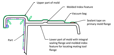
Ask any toolmaker who does tool maintenance, and they will tell you that over time, tooling holes, pins, bushings and other penetrations into or through the tool laminate will begin to leak. When used cycle after cycle, stresses on pin locations, bushings and metal vacuum plumbing/hardware locations all develop microcracking in the adjacent matrix resin that will eventually link up with the microfracture (leak) network. It may be best to use molded features in the mold to provide indexing of the part for subsequent tools used in trimming and drilling operations (Fig. 3).
Multi-piece tools
Fig. 4. This illustration demonstrates the idea of placing multiple pieces of a tool into a parent mold so that vacuum/pressure integrity can be maintained. Photo Credit: Abaris
Instead of splitting a tool into separate pieces with a split-line to accommodate negative draft configurations, consider designing the mold with pieces that are inserted into a “parent” tool for maintaining vacuum/pressure integrity across the split-line (Fig. 4).
From hindsight to foresight
There are many more good ideas for reducing or eliminating leaks in a composite mold. For example, in the 1980s I was part of a team that used a Viton interleaf layer1 in the tool laminate design to mitigate leaks in prepreg autoclave-cured tools. The Viton layer works well at eliminating leaks but requires extra consideration in the laminate design to reduce thermal expansion effects. The point is that with a little knowledge and some foresight, tool designers and fabricators can take extra care ahead of time to produce quality, leak-free composite molds. Remember the motto “prework instead of rework” when fabricating composite tooling.
References
- Reference patent number 4,671,837, “Process for Forming Composite Molds to be Used in the Manufacture of Composite Parts.” Robert B. Stewart, patents.google.com/patent/US4671837
Related Content
Addyx carbon exoskeleton technology enables molded ribs inside hollow composite structures
Using a water-soluble mandrel, carbon exoskeleton opens paradigm for topology-optimized composites, cutting weight, manufacturing time and scrap rate.
Read MoreBladder-assisted compression molding derivative produces complex, autoclave-quality automotive parts
HP Composites’ AirPower technology enables high-rate CFRP roof production with 50% energy savings for the Maserati MC20.
Read MoreMold 3D printing helps automate composite bathtub, shower production
As part of its efforts to automate as much of its production process as it can, Lyons Industries acquired a Massivit 10000 additive manufacturing system to quickly produce high-performance molds and support fixtures.
Read MorePlant tour: Airtech International, Springfield, Tenn., U.S.
Fifty years of supplying materials for composites manufacturing includes custom fabrication and now aims to advance 3D-printed tooling, parts and new resins.
Read MoreRead Next
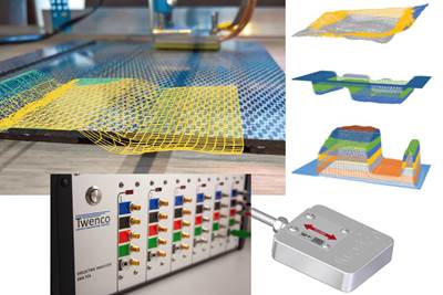
Twenco develops sensors for smart molds and process control in resin infusion and composites welding
Non-invasive DEA and NDT Analyzer for multi-parameter monitoring, QA and control, including real time simulation feed and 3D process visualization across and through composite parts.
Read MoreTroubleshooting thermal design of composite battery enclosures
Materials, electrical insulation and certification are all important factors to consider when optimizing electric battery performance against potential thermal runaway.
Read MoreAll-recycled, needle-punched nonwoven CFRP slashes carbon footprint of Formula 2 seat
Dallara and Tenowo collaborate to produce a race-ready Formula 2 seat using recycled carbon fiber, reducing CO2 emissions by 97.5% compared to virgin materials.
Read More








.jpg;maxWidth=300;quality=90)

