History, myths and urban legends of pultrusion
CW guest columnist and composites industry pultrusion consultant David E. Green tells us that many interesting stories have been told about the early days of pultrusion, and some of them are true.
Sometimes we see new things when looking back. In 1881, a patent was issued for a process that used natural sunlight for UV cure to make artificial leather. This seems quite similar to pultrusion without a curing die, much like the oven-cured and UV-cured pultrusions of today.
In the mid-1940s and early 1950s, as the availability of thermoset resins increased, many industrious minds worked to take advantage of new possibilities. With no Internet available to enhance communications, we can see that the same end goal was reached by independent activities. As a result, several patents of pultrusion-type processes were granted during these early years.
The earliest clue to the “birth” the pultrusion process that I’ve found is the patent by J.H. Watson in 1944 for “Manufacture of a string or the like,” #2,419,328. Then, in 1950, M.J. Meek filed his “Method for fabricating a glass rod,” #2,684,381. Rodger White, in 1952, filed his patent, #2,818,606, for “Manufacture of articles from thermosetting materials.” These were followed by W.R. “Brandt” Goldsworthy in 1953, with his patent #2,871,911, titled “Apparatus for producing elongated articles from fiber reinforced plastic material.” Refinements and variations of the pultrusion process continue to this day.
Many stories of pultrusion development have been told. One I heard is from the old-timers who worked for Glastic Corp. (Cleveland, OH, US). Glastic was the first to provide commercial pultruded products into the marketplace, so the story might have merit. Its process pulled resin-impregnated fibers into an open die and then, while the fibers were stationary, the die was closed and the impregnated fibers were cured. The mold then opened to permit the machinery to pull the cured section of the materials stream from the mold and pull as yet uncured materials into it. This was a stop-and-reset process in which the parts were separated farther down the line. According to this story, on a line that was making a rod-like shape one day, the operator got lazy (or inventive?) and didn’t open the die but rather just pulled the new material into the mold while it was still closed. It worked! So this procedure was perfected and then used to make products sold into the marketplace.
Eventually, Rodger White, a founder and owner of Glastic, wrote his patent, mentioned above, which described this intermittent pultrusion method as a pull-and-purge process. A president of another company told me that, because of that patent, his company, also an early pultruder, had to close its doors to outsiders and claim that they only did continuous pulling and didn’t purge (with the materials of the day, very unlikely).
Another story reportedly occurred in Chicago, where a particular group of pultrusion pioneers had worked for several days to get a small part to run. One day, the part was finally processing and the staff, concentrating its attentions on supporting and maintaining the fragile process conditions and not watching the end of the line, shortly thereafter heard a city cop knocking at the shop’s door. It seems that the part had got out a window, gone over the building next door and was now blocking traffic on the next street over! This is quite believable, because I have seen and heard of unattended machines having similar consequences when an automated cut-off failed.
Raw materials have progressed mostly by adapting products made for other uses. We need to thank the Alaskan oil pipeline for our pultrusion mat. I recall the mats that were first available to pultruders were fluffy and weak and would not work for today’s profiles. To insulate the pipeline so that it didn’t melt the permafrost and sink, Owens Corning (Toledo, OH, US) developed a mat to wrap the pipeline. When the pipeline was completed, the machines and capability were available. Somehow, that capacity and the pultrusion industry found each other. That’s how today’s continuous strand mat was born.
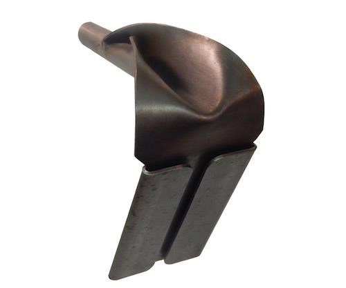
For years there seemed to be a West Coast way and a Midwest way. Sometimes they copied each other; sometimes they shared ideas; and sometimes they hid the same secrets. I recall expanding on a West Coast idea for use in the Midwest: It was a mat-forming guide for a tube. My first encounter in the early 1970s with a somewhat similar guide was from a description and photograph of guides made by Goldsworthy. Those guides provided for one mat to wrap around the part circumference with only one seam running the length of the parts. (We had been doing this on very inside mats, but not on mats with other mats beneath them). In the Goldsworthy designed guide, the mat came from behind the guides in a plane oblique to the material direction and did place a layer on the outside of the product. They were a step above others that were in use. Because mat will stretch and fabric will wrinkle, they were quite long. The extra length allowed for forming with more uniform mat stretching and reduced the mat’s tendency to wrinkle. These guides did allow for one circumferential mat to enter the raw material stream and form with other materials beneath them, but problems remained.
I was at Pultrusions Corp. (Aurora, OH, US) at the time and Hugo, the toolmaker, was a very talented person with more than 60 years’ experience (he went on to provide tooling for others, and I don’t think that he stopped until he was around 100). He duplicated Goldsworthy’s guides, but the fact that they permitted mats to stretch was ultimately undesirable. Setting out to correct that, I took a piece of paper the width of the mat, formed one end into a tube and found that the paper had a tendency to naturally curve, going back on itself to form the round, tube-like shape. When I took this formed paper to Hugo and asked if we could do this, he used his genius to turn that concept into metal and made a guide for mats that was extremely effective. I called it a reverse forming guide (see photo below) because the mat enters the guide through the flat portion, goes around the corner and enters the round portion, encircling, in the process, the continuous fibers and other reinforcements that are already gathered together and passing through the guide. Others have called it a constant velocity guide, which is a pretty good title because the “path” the mat travels through the guide, as it changes from flat to circumferential, remains at a constant width regardless of its shape, and this helps reduce the mat’s tendency to distort or stretch as it travels through the guide.
In the early days, every raw material salesman or engineer that first saw those guides said that they were the cause of all problems. As time passed, they became the standard guides and were promoted by those same people.
One of the best-formed guides of this type was made overnight by a sewing machine guide maker in Missoula, MT, US. With nothing more than my spreadsheet calculations for the blank and a smaller guide to look at, he was able to make a finished, working model. This shows that if we use the fabrication expertise readily available to us today and take the initiative to search for improvements, we can write tomorrow’s history and, perhaps, provide tomorrow’s legends.
Related Content
Sulapac introduces Sulapac Flow 1.7 to replace PLA, ABS and PP in FDM, FGF
Available as filament and granules for extrusion, new wood composite matches properties yet is compostable, eliminates microplastics and reduces carbon footprint.
Read MoreThe potential for thermoplastic composite nacelles
Collins Aerospace draws on global team, decades of experience to demonstrate large, curved AFP and welded structures for the next generation of aircraft.
Read MoreBio-based acrylonitrile for carbon fiber manufacture
The quest for a sustainable source of acrylonitrile for carbon fiber manufacture has made the leap from the lab to the market.
Read MoreThe lessons behind OceanGate
Carbon fiber composites faced much criticism in the wake of the OceanGate submersible accident. CW’s publisher Jeff Sloan explains that it’s not that simple.
Read MoreRead Next
CFRP planing head: 50% less mass, 1.5 times faster rotation
Novel, modular design minimizes weight for high-precision cutting tools with faster production speeds.
Read MoreVIDEO: High-rate composites production for aerospace
Westlake Epoxy’s process on display at CAMX 2024 reduces cycle time from hours to just 15 minutes.
Read MorePlant tour: A&P, Cincinnati, OH
A&P has made a name for itself as a braider, but the depth and breadth of its technical aptitude comes into sharp focus with a peek behind usually closed doors.
Read More






.jpg;maxWidth=300;quality=90)


