Automotive front axle: A glass act
The development of glass-fiber reinforced car axle is a sign of the new, expanded role composites will play in the design of future automobiles.
Design Results:
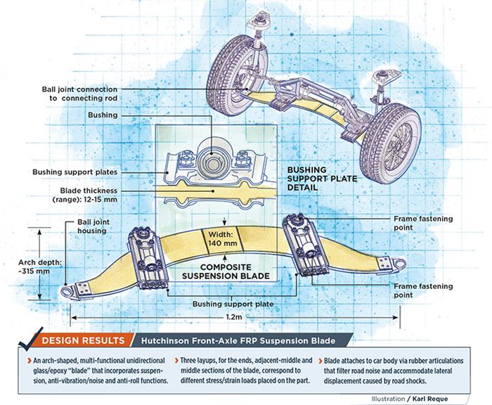
- An arch-shaped, multi-functional unidirectional glass/epoxy “blade” that incorporates suspension, anti-vibration/noise and anti-roll functions.
- Three layups, for the ends, adjacent-middle and middle sections of the blade, correspond to different stress/strain loads placed on the part.
- Blade attaches to car body via rubber articulations that filter road noise and accommodate lateral displacement caused by road shocks.
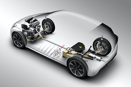
In what could prove to be a first in the commercial automotive market, industrial transportation supplier Hutchinson (Paris, France) has developed front and rear axles made from glass-reinforced composites for the new Peugeot 208 FE, a hybrid electric concept car that reportedly consumes just 1.9L of gasoline per 100 km. The switch from a traditional metal axle/suspension system to one based on composites resulted in a weight savings of 20.4 kg, or roughly 40%. Peugeot, in collaboration with Hutchinson parent company Total (Paris), designed the car to explore potential ways to meet the stringent European regulations that stipulate that automobiles emit less than 90g of CO2/km by 2020. The 208 FE easily meets this target, emitting a reported 49g of CO2/km, an apparent world record for a pure (non-plug-in) hybrid.
Hutchinson designed the axles, drawing on its experience as a materials formulator and manufacturer of vibration control technology for the automotive, rail and aerospace industries. Hutchinson terms the structural composite heart of the axles a “multi-functional suspension blade,” because it is designed to incorporate in one part, four critical functions: suspension, steering, anti-vibration/noise and anti-roll. During the development process, design engineers were able to integrate/eliminate 12 distinct parts, including springs, spring holders, anti-roll bar, anti-roll bar fittings, the connecting rods of the anti-roll bar and the wishbone (part of the steering) elements.
The radically new suspension actually has its origins in a unit Hutchinson built for another European car manufacturer 20 years earlier. Bertrand Florentz, technical director at Hutchinson’s Composites Technical Centre (CTeC), recalls that part was production-ready but cancelled at the last minute in favor of a traditional steel suspension. Faced with the coming 2020 emission standard and the penalties for failing to meet it, market conditions have changed considerably for today’s automaker, and Hutchinson’s experience with the earlier suspension enabled it to quickly get up to speed with a new, unique design for Peugeot’s 208 FE.
Loads determine design
The first consideration when designing an automotive suspension is that the part assembly is subject to both static loads (applied by the car’s stationary weight) and dynamic loads (those created while driving) corresponding to tension, compression and shear forces distributed in all three spatial axes: longitudinal, vertical and lateral. The dynamic forces imposed while driving can be up to five times greater than the car’s static load; thus dynamic loads are the determining factors in the part’s critical structural dimensions and overall design, Florentz says.
Hutchinson’s preliminary “macro” design solution to the problem of these multiaxial loads was to simulate the primary suspension structure with a beam-homogenized orthotropic model. The beam orthotropic model served as a “baseline” that allowed engineers to target the localized stiffness properties necessary to meet the vehicle’s basic static load.
A material is orthotropic if its mechanical or thermal properties are unique and independent in three mutually perpendicular directions, as opposed to an isotropic material in which the properties are the same in all directions. Additionally, a material can have a homogeneous or non-homogeneous microstructure. A material such as rolled steel is naturally orthotropic and homogeneous. Designing a homogeneous orthotropic composite is a matter of constructing a laminate with the same “micro-structure” (i.e., materials, in this case, an epoxy resin) with a majority of unidirectional glass fibers, in a layup constituting varying thicknesses and directions. Such a structure would allow design engineers to account for various distortions and loads in each of the three independent axes by adding or subtracting reinforcement in specific areas after the part had been modeled in finite element analysis (FEA).
Accordingly, the second step in the design process was the detailed finite element model (FEM) simulation of the suspension at the Hutchinson Research Centre. Here, the simulation was used to model the stiffness of the composite blade and provide the detailed architecture of the layup, including orientation of fabric and local thicknesses. The result is a blade design that features three layups: layup one, on each end of the blade, where the ball joint attaches to the pillars (thicker and more particularly devoted to the wheel guidance with a high longitudinal stiffness); layup two, in the two side-center sections attached to the rubber-mounted, steel axle brackets; and layup three, in the center section between the brackets (thinner and more particularly dedicated to the vertical stiffness of the suspension).
The load cases taken into account in the FEA simulation were vertical (symmetrical and asymmetrical), longitudinal, transverse, cornering, side-impact and fatigue. The simulation outputs were stiffness, displacements and kinematics of the blade in all directions, as well as local stress and strain for the resin and the fibers. Stresses and strains were then compared to the material allowables obtained by the lab department, including necessary “knockdown” factors.
In a parallel development, researchers conducted a comprehensive materials characterization, using test specimens of the laminate and neat resin. Process parameters specific to the materials and part production — e.g., resin transfer molding (RTM), total heat of reaction, thermal expansion and shrinkage (in all three axes) and fiber concentration — were calculated from measurements taken via differential scanning calorimetry (DSC), contact angle measurements and dynamic mechanical analysis (DMA). These data were used to produce a viscoelastic model of the suspension blade, which in turn was imported into ABAQUS FEA software (Dassault Systèmes, Waltham, MA, US). Thermal and mechanical analyses were carried out to identify thermal “hot spots” during molding, as well as to calculate and predict process-induced deformations and residual stresses during the cure cycle, toward the goal of optimizing processing conditions when the part design was finalized and parts were serially molded on regular production tooling and equipment.
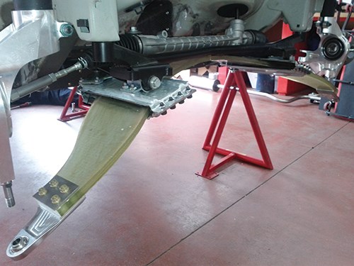
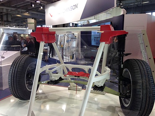
Although Hutchinson designed front and rear composite axles for the Peugeot 208 FE, the front axle is the more complex case because of the added element of steering. The final design of the suspension consisted of an arch-shaped main structural glass-fiber reinforced blade with a thickness ranging from 12 mm to 15 mm, and fiber volume fraction of more than 50%. The blade is approximately 1.2m in length by a nominal 140 mm in width with an arch “depth” of about 315 mm. In the process of eliminating all the aforementioned parts, the composite axle/suspension design integrated all of the functions of a traditional metal suspension as follows: The arch-shaped suspension blade is installed on the car during assembly in its “pre-compressed” shape and functions as a single spring across the width of the car’s front end to absorb road shocks. Each side of the composite blade is fitted to the car’s body-in-white (BIW) with a pair of rubber articulations, one vertical and one longitudinal. As the blade bends or compresses in reaction to road shocks, it is lengthened in the transversal axis between those two pairs of fixations. The rubber mounts provide the necessary lateral displacement flexibility to accommodate this lateral elongation, and they also furnish additional filtering of road vibration and noise. These articulations are integrated to a pair of steel soles that encapsulate each side of the blade (see drawing, at left).
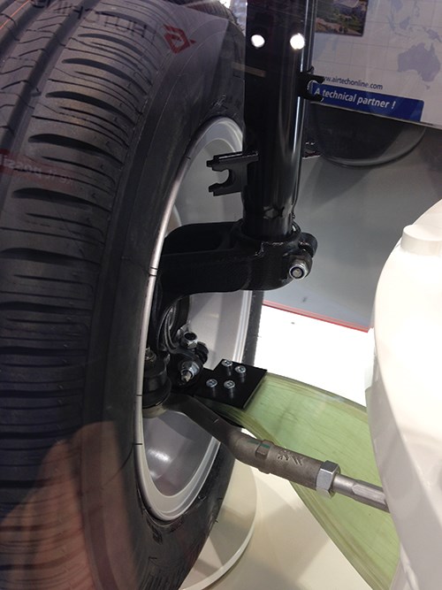
Each tip of the blade is fitted with a steel ball joint. The ball joints, in turn, are fitted with connecting rods (tie bars), which are attached to the car via the shock absorbers. It is at these points of attachment that the blade experiences the highest loading forces and, therefore, the blade is designed with additional reinforcement in this area. In place of anti-roll bars, the blade itself functions as an anti-roll mechanism as a result of its inherent bending stiffness and its fixations symmetry. In fact, due to the symmetry of the deformation, when the left wheel is moved upward, the right wheel also moves upward, which is actually the definition of an anti-roll connection. Steering is conventional and separated from the blade, with a steering rack attaching the wheel pivots directly through left and right connecting rods.
Florentz says designing and manufacturing a composite axle/suspension involved at least five times the engineering effort necessary to design the same component in metal. In part, the extra time was necessary because steel is a legacy material with plenty of archived test and qualification data, but for the composite part, the final material had to be characterized after aging, simulated and post-treated layer by layer, from data acquired from fatigue campaigns done on aged coupons. Assuming composites use in similar applications, it is plausible that much of the extra engineering time could be shaved off as materials qualifications, testing and simulation work transfer from one project to another.
While the technology is still considered conceptual, this application is noteworthy and potentially significant. Long considered unsuitable for structural applications in commercial vehicles, composites have fought an uphill battle to prove their mettle as a replacement for metal. Perhaps with this significant step, automakers and consumers can begin to judge for themselves.
Related Content
Thermoplastic composites: Cracking the horizontal body panel nut
Versatile sandwich panel technology solves decades-long exterior automotive challenge.
Read MorePEEK vs. PEKK vs. PAEK and continuous compression molding
Suppliers of thermoplastics and carbon fiber chime in regarding PEEK vs. PEKK, and now PAEK, as well as in-situ consolidation — the supply chain for thermoplastic tape composites continues to evolve.
Read MoreManufacturing the MFFD thermoplastic composite fuselage
Demonstrator’s upper, lower shells and assembly prove materials and new processes for lighter, cheaper and more sustainable high-rate future aircraft.
Read MoreThe potential for thermoplastic composite nacelles
Collins Aerospace draws on global team, decades of experience to demonstrate large, curved AFP and welded structures for the next generation of aircraft.
Read MoreRead Next
Developing bonded composite repair for ships, offshore units
Bureau Veritas and industry partners issue guidelines and pave the way for certification via StrengthBond Offshore project.
Read More“Structured air” TPS safeguards composite structures
Powered by an 85% air/15% pure polyimide aerogel, Blueshift’s novel material system protects structures during transient thermal events from -200°C to beyond 2400°C for rockets, battery boxes and more.
Read MoreVIDEO: High-volume processing for fiberglass components
Cannon Ergos, a company specializing in high-ton presses and equipment for composites fabrication and plastics processing, displayed automotive and industrial components at CAMX 2024.
Read More


.jpg;maxWidth=300;quality=90)


