Block shear strength of adhesive bonds
Dr. Don Adams describes two methods (ASTM D 905 and ASTM D 4501) for loading adhesive bonds in direct shear while minimizing undesirable peel and through-thickness tensile stresses.
There are a variety of test methods that characterize the properties of adhesive bonds between two similar or dissimilar material layers. The differences between the methods relate to the stress states that they induce in the adhesive. For example, if one layer (adherend) is sufficiently flexible, it can be peeled off the other, more rigid, adherend. This peel test induces a complex stress state within the adhesive that is representative of what could happen in service, and thus this test can provide useful comparative data. Likewise, direct tension through the thickness of the adhesive might occur in service — accidentally or deliberately. To test the strength of an adhesive bond in this stress state, a bonded test coupon can be gripped and pulled apart in through-thickness tension.
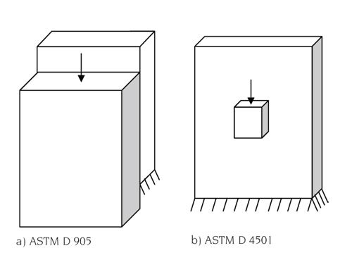
However, adhesive bonds are typically designed to be loaded in direct shear, that is, by a loading mode that applies stress parallel to the bond line, causing one adherend to want to slide across the other. This loading results in efficient load transfer from one adherend to the other, leading to an efficient joint design. The most direct, and perhaps the most obvious, method of measuring the shear strength of the adhesive bond between two adherends is to bond the two adherends together and then shear them apart. The primary issue, then, is how to grip the adherends properly so that a shear stress can be induced in the adhesive while minimizing what would be, in this case, undesirable peel and through-thickness tensile stresses. Although commonly used, and often representative of an actual bonded joint design, a lap joint loaded by pulling two thin adherends apart also induces these undesirable secondary stresses. Therefore, two alternate shear-loading methods and accompanying test fixtures were developed that use comparatively thick adherends and push rather than pull when they apply the stress load. Both are governed by ASTM standards. Typical test specimens are shown in Fig. 1.
The first of these standards, ASTM D 9051, was originally published in 1947 as a test of adhesives for bonding wood products and thus is often referred to as a lapped block shear test. Its use has been extended to other material forms as well, including composite laminates. The specimen consists of two blocks with the same length and width, but not necessarily the same thickness, bonded together in a slightly staggered (lapped) configuration, as shown in Fig. 1(a). The sole purpose of the staggered joint is to ensure that one adherend is supported by the base of the test fixture, and the other is loaded by the downward-moving head.
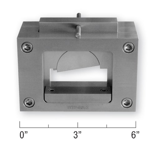
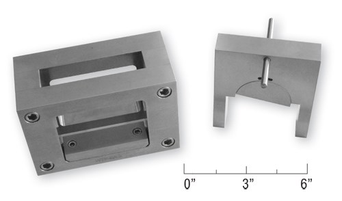
ASTM D 905 specifies a specimen that comprises two blocks identical in size: 45 mm long by 50 mm wide (1.75 inches by 2 inches), staggered 6 mm/0.25 inch. Obviously these dimensions can be varied, if desired. For example, it may be desirable to use a specimen of another size when testing a different class of material, such as a composite, ceramic or metal. But results obtained using specimens of one size will not necessarily be the same as those obtained using specimens of another size. All specimens that will be compared for strength, therefore, must be the same size, but they need not conform to the ASTM standard size. A typical test fixture, designed to accommodate a specimen of the standard size, is shown assembled in Fig. 2 and with the loading head removed in Fig. 3. It incorporates a semicircular, pivoting loading disk, which helps ensure that the compressive loading is applied uniformly across the specimen’s width. The pin that passes through the loading head is simply a handle used to raise and hold the loading head out of the way while a specimen is installed in the fixture.
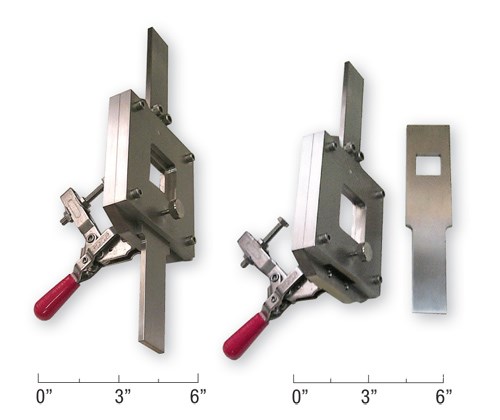
The second standard, ASTM D 45012, uses a specimen like the one shown in Fig. 1(b). Issued in 1985, this standard was originally developed for the adhesive bonding of plastics. It, too, can be used to test bonds between adherends of other materials, including fiber-reinforced composites. The assembled fixture is shown in Fig. 4, and Fig. 5 shows the loading blade removed. The principle of operation is much like that of a guillotine. With the loading blade in place, the specimen shown in Fig. 1(b) is installed from the left side, with the lower edge of the plate portion of the specimen resting on the lower edge of a cutout in the back side of the fixture and the small block of the specimen projecting into the cutout in the loading blade. The toggle clamp is then closed to hold the plate portion of the specimen in place. When the upper and lower arms of the fixture are pulled apart, the small block is sheared off the plate.
Again, the sizes of the plate and block are arbitrary, with the same restrictions as previously discussed. ASTM D 4501 does offer general size guidelines for various types of test materials. The fixture shown in Figs. 4 and 5 is sized to accommodate a plate up to 75 mm/3 inches square and a block up to 25 mm/1 inch square. The specimen thicknesses are arbitrary because the fixture is capable of accommodating a wide range of thicknesses.
The modulus of elasticity of most adhesives is somewhat, if not considerably, lower than that of the adherends that they will bond together. This certainly includes composite laminate adherends. Also, the ductility of the adhesive is often greater than that of the adherends. Thus, although some shear stress concentrations are induced at the leading and trailing edges of the adhesive bond during the initial (elastic) portion of the sliding (shear) load, these stress concentrations tend to be significantly reduced as the nonlinear (plastic) strain increases during subsequent loading to failure. Thus, the average shear strength, calculated from the failure load, can produce a very reasonable value for the actual shear strength of the adhesive and, correspondingly, the strength of the bonded joint.
A practical advantage of these block shear tests is that the specimens are simple and can be prepared inexpensively. Thus, a large number of adhesive and adherend material combinations and adhesive bondline thicknesses can be screened quickly and efficiently.
References
1ASTM D 905-08 (2008), “Strength Properties of Adhesive Bonds in Shear by Compression Loading,” ASTM International (W. Conshohocken, Pa.), (originally issued in 1947).
2ASTM D 4501-01 (2001; reapproved 2009), “Shear Strength of Adhesive Bonds Between Rigid Substrates by the Block-Shear Method,” ASTM International (W. Conshohocken, Pa.), (originally issued in 1985).
Related Content
Syensqo introduces AeroPaste 1003 aerospace adhesive
Two-part room-temperature paste increases high-rate assembly and joining efficiencies when bonding metallic and composite parts.
Read MoreBiDebA project supports bio-based adhesives development for composites
Five European project partners are to engineer novel bio-based adhesives, derived from renewable resources, to facilitate composites debonding, circularity in transportation markets.
Read MorePRF Composite Materials introduces primer, adhesive films
Novel RFA570 eXpress cure adhesive film and RF Primer are compatible with PRF’s full range of epoxy prepregs formulations.
Read MorePro-Set named official materials supplier for New York Yacht Club American Magic
Competitive sailing team prepares for the 37th America’s Cup beginning in August 2024 with adhesives, resins and laminate testing services for its AC75 monohull construction.
Read MoreRead Next
All-recycled, needle-punched nonwoven CFRP slashes carbon footprint of Formula 2 seat
Dallara and Tenowo collaborate to produce a race-ready Formula 2 seat using recycled carbon fiber, reducing CO2 emissions by 97.5% compared to virgin materials.
Read MoreDeveloping bonded composite repair for ships, offshore units
Bureau Veritas and industry partners issue guidelines and pave the way for certification via StrengthBond Offshore project.
Read More“Structured air” TPS safeguards composite structures
Powered by an 85% air/15% pure polyimide aerogel, Blueshift’s novel material system protects structures during transient thermal events from -200°C to beyond 2400°C for rockets, battery boxes and more.
Read More
