Composite Accumulator Bottles Perform In Service
A riser tensioning system for a TLP consists of a tensioning ring and framework, with four to eight hydraulic cylinders — each with an attached pressure vessel or “accumulator bottle” — to support and allow movement of the rigid riser pipe. Installed in the riser wellbay, this primary structural system is desi
A riser tensioning system for a TLP consists of a tensioning ring and framework, with four to eight hydraulic cylinders — each with an attached pressure vessel or “accumulator bottle” — to support and allow movement of the rigid riser pipe. Installed in the riser wellbay, this primary structural system is designed to accommodate platform motion while minimizing movement of the risers. When the platform rises, the cylinder stroke extends and hydraulic fluid and nitrogen in the accumulator bottle flows into the cylinder. When the platform falls, the stroke retracts and the fluid and gas are forced back into the bottle. The pressure vessels must be extremely robust to contain the high pressures that are required.
In the mid-1990s, Lincoln Composites (Lincoln, Neb.. U.S.A.) produced 104 50-gallon carbon and fiberglass accumulator bottles (CABs) for the Mars TLP in the Gulf of Mexico, four for each of 24 production wellbays, plus eight for the drilling riser. The all-composite CAB, certified under the American National Standards Institute (ANSI) AGA NGV2 standard for natural gas vehicles, is defined as a hybrid glass/carbon fiber- reinforced epoxy composite shell, filament wound over a high-density polyethylene (HDPE) non-loadbearing liner. An HDPE liner offers several advantages over a metallic liner — notably low permeation rate, lower cost, substantially reduced weight, shorter lead-time for procurement and a virtually unlimited fatigue life. Johnson says that based on measured permeation rates, a vessel with an HDPE liner pressurized to 3,600 psi/250 bar with air would lose only about 0.01 psi per year.
The CAB incorporates 316L stainless steel polar bosses; the domed ends of the HDPE liner are injection molded around the threaded bosses in a process (patented by Lincoln) that maintains a gas-tight seal without any bonding or other secondary fabrication of the liner-to-boss joint. “For a corrosive environment, it’s advantageous to encapsulate metal fittings wherever possible,” Johnson explains. The two domed ends are heatwelded to an extruded center cylindrical section. The external weld beads are removed after fusion, and the liner is inspected before winding begins.
Wind axis stubs inserted into the polar bosses allow the liner to be “chucked” into the winding machine, where it serves as a mandrel on Lincoln’s CNC multi-axis filament winder. As fibers are impregnated with resin during the winding process, resin percentage is controlled within 2 percent by weight, Johnson says. Up to six different filament winding angles are used. “When you filament wind a pressure vessel, the angle changes as you go through the part thickness in order to react the pressure end loads,” explains Johnson. High-modulus carbon promotes part strength while the more elastic glass provides good damage tolerance. Glass fibers also offer a cost-effective means of building up the wall thickness of the laminate, which boosts resistance to burst pressures and increases the stability of the vessel’s cross-section while cushioning external impact.
With a design pressure of 3,000 psi/210 bar, the filament wound tanks qualify for the offshore application per ASME Boiler and Pressure Vessel Code, Section X, fiber-reinforced plastic pressure vessels. Section X requires that the vessel be cycled from atmospheric pressure to design pressure a total of 33,000 times at temperatures ranging from - 20°F/-29°C to 150°F/66°C and calls for a safety factor of five times the design pressure — or 15,000 psi/1,040 bar burst pressure. Before production began, a design verification test unit was fabricated and burst at room temperature to provide a preliminary evaluation of both the vessel performance and the manufacturing plan. Additionally, each CAB production unit was subjected to a series of acceptance tests to verify liner and composite integrity, including a proof pressure test, a weight and internal volume calculation and a final dimensional inspection.
To meet this requirement, Lincoln designs the CABs for a minimum virgin burst pressure of 16,500 psi/1,150 bar to account for potential variations in fiber strength and the manufacturing process. At greater than 5:1, the demonstrated safety factor for the hybrid glass/carbon-reinforced CABs now exceeds that necessary to guarantee virtually unlimited useful life, Johnson says. “If the actual strength of the materials were considered in the factor of safety, the vessel would be less expensive to make and less expensive to buy,” he adds. Johnson would like to see the ASME code updated to reflect actual material strengths. He points out that when the ASME code was adopted in 1977, it was based on fiberglass alone. “A factor of safety of five, based on glass fiber strength at that time, was not inappropriate at all,” he explains. “But since then, both the strength and strength retention of fiberglass have been improved. Additionally, it is often hybridized with carbon or aramid fibers, which significantly boosts demonstrated strength of the vessel.” To meet the high burst pressure requirement, the vessel wall of a typical CAB cylinder might contain more than 50 plies of material, resulting in wall thickness twice that of an NGV tank of equivalent size. Fatigue studies indicate that, at a safety factor of 5, carbon fiber has a projected reliability of 0.9999 for a lifetime in excess of 10,000 years and a cyclic fatigue life in excess of 1012 cycles.
As of mid-2001, Lincoln had CABs of various capacities on five platforms: Shell’s Mars (50 gallon), Ram-Powell (65 gallon), Ursa (86 gallon) and Brutus (86 gallon); and BP’s Marlin project (65 gallon). All are TLPs in the Gulf of Mexico, in about 3,000 ft/900m of water, and all have 3,000 psi/210 bar rated pressure.
Related Content
Composites end markets: Energy (2024)
Composites are used widely in oil/gas, wind and other renewable energy applications. Despite market challenges, growth potential and innovation for composites continue.
Read MoreRecycling end-of-life composite parts: New methods, markets
From infrastructure solutions to consumer products, Polish recycler Anmet and Netherlands-based researchers are developing new methods for repurposing wind turbine blades and other composite parts.
Read MoreHonda begins production of 2025 CR-V e:FCEV with Type 4 hydrogen tanks in U.S.
Model includes new technologies produced at Performance Manufacturing Center (PMC) in Marysville, Ohio, which is part of Honda hydrogen business strategy that includes Class 8 trucks.
Read MoreECOHYDRO project to enable recyclable composites for hydrogen storage
With the involvement of two schools from the Institut Mines-Télécom, the 4-year project aims to improve the intrinsic properties of a composite material based on Elium via four concrete demonstrators.
Read MoreRead Next
Petrobras Pioneers Topside Composites
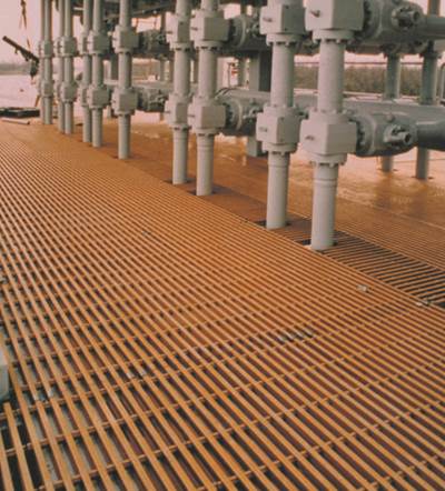
Petrobras (Rio de Janeiro, Brazil) was the first major oil company to experiment with molded gratings in the 1980s, though these early products proved unsatisfactory due to wide variations in mechanical properties. However, advances in pultrusion and filament winding technology coupled with the availability of
Read MoreOther Applications Expand
A growing area in the offshore world is the refitting or “recycling” of older oil platforms to support additional production. A particularly active area for recycling is in the North Sea, where additional pipelines can be run to existing rigs for about $1 million (as opposed to spending $20 million for a new r
Read More
