Composite pontoons undergird update of 1820s-vintage floating bridge
Modular composite flotation system triples potential lifespan of New England town’s signature single-lane auto/pedestrian timber bridge.
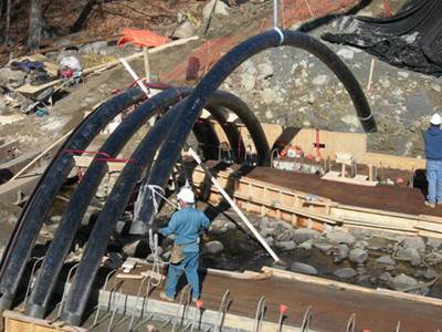
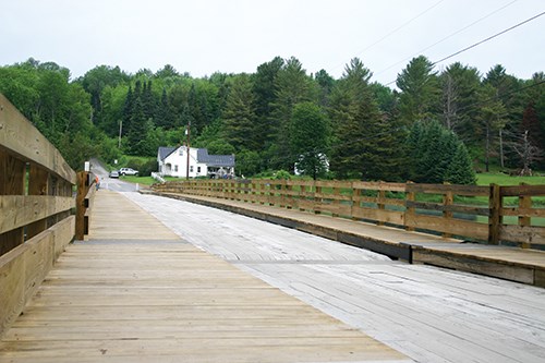
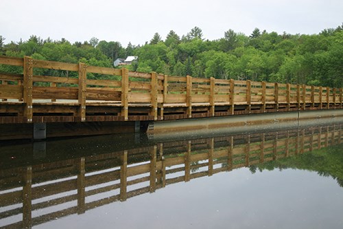
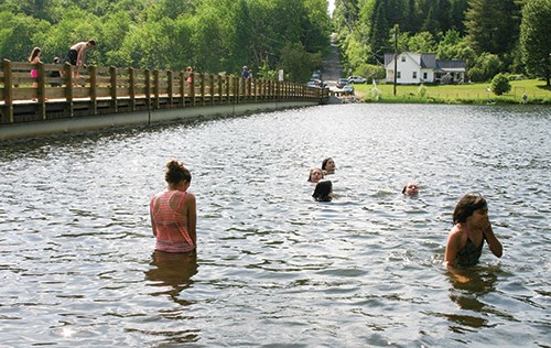
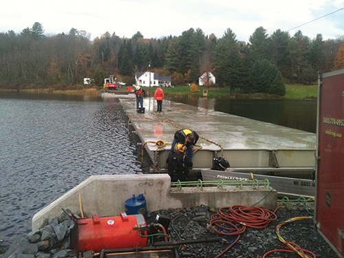
In the central Vermont town of Brookfield (pop. 1,292), the world’s first floating fiber-reinforced polymer (FRP) bridge has replaced a 1978 version that carried state Route 65 traffic over Sunset Lake (see last two photos, at left). Designed by T.Y. Lin International (San Francisco, CA, US), it is the eighth version of a floating log bridge built in 1820 after a resident fell through winter ice and drowned while crossing the lake nearly two centuries ago. It has since been the focal point of the town’s life. Construction of the new 97m long, 6.7m wide, US$2.4-million single-lane Brookfield Bridge began in April 2014 and was complete before its opening, Memorial Day weekend 2015.
Replacement became necessary when 380 of the 50-gal barrels that kept it afloat began to leak. “The plastic styrofoam-filled barrels were becoming saturated and deteriorating,” says Jennifer Fitch, project manager at the Vermont Agency of Transportation (VTrans). As the barrels lost flotation and the timber got saturated, the bridge gradually sank and was finally closed in 2008. Its use had been seasonal, recalls John Benson, chair of the Brookfield Selectboard and a registered civil engineer, so “there were no plans for quick replacement, since only 110 cars cross the bridge daily in summer.”
But two years later, increasing awareness of the bridge as a community landmark and a contributing element to Brookfield’s listing on the National Historic Register spurred formation of a floating bridge committee. Its members — including representatives of the town, VTrans and the US Federal Highway Admin. (FHWA) — identified the need for a state-of-the-art flotation system with a 100-year life, says Fitch.
Design evolution
VTrans structures program manager Wayne Symonds first toyed with using FRP for the bridge while at the Maine Composites Showcase at the University of Maine (UMaine, Orono). He visited some of Maine’s first bridge-in-a-backpack structures (designed at UMaine, see “Bridge cost cut with inflatable arches" under "Editor's Picks" at top right) and the manufacturing facilities at Kenway Corp. (Augusta, ME), and Brunswick, ME-based Harbor Technologies. The latter was building floating docks for cruise ships. Symonds recalls thinking, “If … cruise ships can bump into them, but they rebound without damage from impact, then a refined version of this technology could work for Brookfield with the traffic and ice loading.”
The initial ideas for a pontoon-based buoyancy design came from research engineers Olivia and Xenia Rofes at UMaine’s Advanced Structures and Composites Center (ASCC). “UMaine came up with the initial cross-sectional shape and helped us out as material property experts as we moved forward with final design,” says Josh Olund, bridge engineer at T.Y. Lin’s Falmouth, ME, office.
Although concrete pontoons were considered, concrete was ruled out because it would have required dredging along the shore to accommodate what would have been 3m-deep pontoons. Specialized trucks and cranes also would have been necessary for transport and installation. “We managed everything inside the right-of-way with minimal environmental impacts,” Fitch says of the more manageable FRP, adding, “Had we gone with concrete, it would have taken longer to complete the design phase.”
“FRP was a top pick since few materials have the ability to provide such longevity,” Fitch sums up. “It doesn’t crack easily; it can handle ice pressures; and with the addition of UV-9, an inhibitor chemical, it should not degrade easily.”
The greatest design challenge was working with unknowns, Olund says. Because design codes for FRP bridges do not exist, the team worked with VTrans and UMaine to examine available guidance and research papers and developed its own set of criteria, using those guides as a foundation. “Every single step of the way, we had to reinvent how to approach design,” he recalls.
T.Y. Lin also determined bridge loading conditions, including ice pressures, live-load configurations (pedestrian and vehicle) and buoyant-service capacity. During the winter of 2012-2013, ASCC’s Sanchez set up sensors at the bridge site to record the pressure developed by the ice on the lake’s surface against the existing flotation system’s vertical surfaces. And as FHWA required for the new bridge, the design team increased the load capacity of the structure, designing for the larger of a single 12-ton truck or 384 lb/linear ft for cars crossing the bridge, Olund explains. “Historically, the bridge had been posted for 3 tons, but it’s unclear if this was truly its design capacity.”
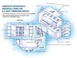
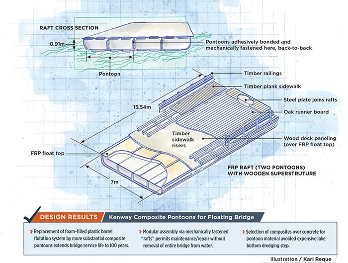
To make construction, transport and installation practical, the FRP portion of the bridge structure was designed in five separate but identical 15.54m long by 7.01m wide sections called rafts (see drawing, above) each formed from two buoyant FRP pontoon structures, assembled back-to-back. Assembled rafts then would be bolted together, end-to-end, using steel splice-plates designed by T.Y. Lin, to form a monolith, undergirding the entire length of the wooden bridge. “It actually acts as one long beam, with timber on top — this is new for a bridge application,” adds Olund.
To prevent water overflow that had degraded the lifespan of the previous bridge’s timber decking and made it slippery for auto traffic, the team designed rotating on/off ramps with unique bearings and joints to permit the bridge to rise and fall with the lake’s natural 1.7m level fluctuations.
To enable the most cost-effective solution possible, the design team elected not to dictate specific materials or substantially high material properties. “This allowed the fabricators to have flexibility in meeting project goals with materials and practices they were comfortable with,” Olund explains.
Pontoon fabrication
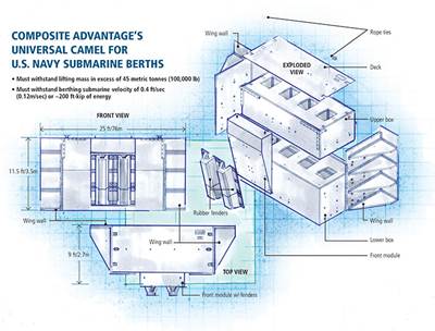
During pontoon fabrication, Kenway Corp. applied techniques it had used previously for “marine camels” — giant floating fenders that protect piers in submarine berths (see “Composite submarine camels win with long-term durability” under "Editor's Picks"). “The same fiberglass, vinyl ester resin and flotation foam were used as on camel fenders,” says Kenway senior project engineer Jake Marquis. After design completion, the Kenway team had to calculate the number of internal members necessary to meet stiffness and strength requirements in the pontoon sections, and then determine the pontoon shell thickness.
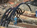
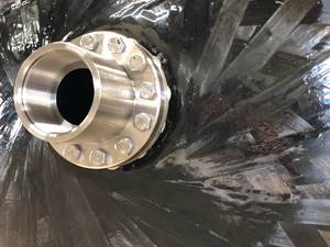
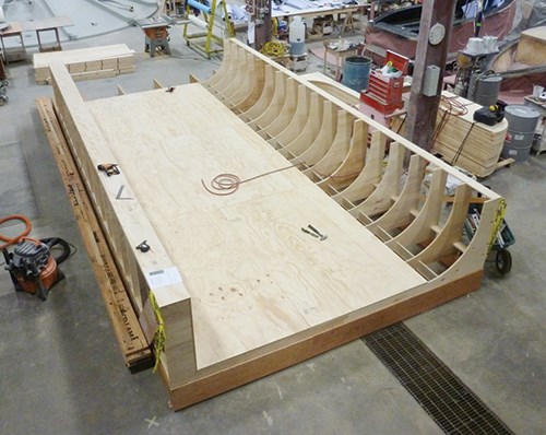
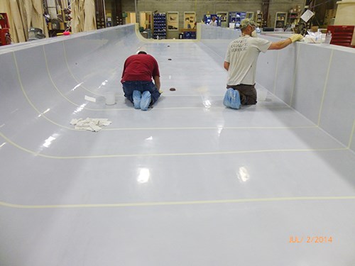
Kenway molded 10 identical pontoons, using a hollow mold constructed of CNC-machined plywood frames (see photos, top left and center). First, the bottom and sides of the hull were molded by laying in dry fiberglass, supplied by T.E.A.M. Inc. (Bristol, RI, US), and vacuum-infusing the layup with vinyl ester resin from Interplastic Corp. (St. Paul, MN, US). After cure, separately infused interior bulkheads were bonded into position using two-part Plexus methacrylate adhesive (ITW Plexus, Danvers, MA, US) to form a grid that was subsequently filled with flotation foam before an infused fiberglass top was bonded to the pontoon hull.
During fabrication, ASCC ran tests to verify the material properties of the composite laminates produced at Kenway for construction of the pontoons, and a series of tests to evaluate the pin-bearing strength of the composite flanges that connect the sections of the bridge. “These results were used to verify that the flanges had the strength to perform as required for the bolted joints,” says Tom Snape, ASCC research engineer.
“After fabricating the pontoons, the Kenway crew staged them in their yard, matching up the [splice-]plates and drilling more than 1,000 bolt holes before delivering them to the bridge site,” Marquis says. The estimated weight of a single raft (two pontoons),
including foam filling, but no attachment hardware, is 11,570 kg.
Bridge installation
At the bridge site, before pontoons began to arrive, crews removed the old bridge structure and installed cofferdams before constructing new concrete abutments. “Putting a cofferdam on a ledge [at one end] was challenging, but we overcame it,” says Paul Holloway, project manager at Miller Construction (Windsor, VT, US).
Beginning in August 2014, Miller Construction began joining pontoons and launching rafts, as they arrived. Pontoons were delivered to the bridge site two at a time, as they were molded and finished, over a four-month period, Holloway says.
“We made a fabrication table out of steel girders and when the pontoons showed up on the flatbed truck, we unloaded them with a crane and put them on the fabrication table where they were bonded together,” Holloway says, using Plexus methacrylate adhesive.
“Three tension rods passed through both pontoons, with a nut on each end to squeeze them together while they are glued,” explains Marquis. “Crews spliced them together and installed the last raft in early December just before the lake froze,” Holloway recalls. Although the pontoons are expected to last for 100 years, the modular raft design of the Brookfield Bridge will permit relatively easy maintenance or replacement of pontoon sections in the event of damage without pulling the entire bridge out of the water.
“Our project created design criteria and specifications for FRP pontoon construction that could be used as a basis for future projects with similar characteristics,” Olund says. But he predicts the most direct technology transfer for the floating pontoon system likely will be in the marine industry, for floating docks, wharfs, barges, pedestrian bridges and temporary military bridges.
Related Content
Sulapac introduces Sulapac Flow 1.7 to replace PLA, ABS and PP in FDM, FGF
Available as filament and granules for extrusion, new wood composite matches properties yet is compostable, eliminates microplastics and reduces carbon footprint.
Read MorePlant tour: Joby Aviation, Marina, Calif., U.S.
As the advanced air mobility market begins to take shape, market leader Joby Aviation works to industrialize composites manufacturing for its first-generation, composites-intensive, all-electric air taxi.
Read MoreWelding is not bonding
Discussion of the issues in our understanding of thermoplastic composite welded structures and certification of the latest materials and welding technologies for future airframes.
Read MoreInfinite Composites: Type V tanks for space, hydrogen, automotive and more
After a decade of proving its linerless, weight-saving composite tanks with NASA and more than 30 aerospace companies, this CryoSphere pioneer is scaling for growth in commercial space and sustainable transportation on Earth.
Read MoreRead Next
Bridge cost cut with inflatable arches
Stay-in-place composite formwork shortens installation, doubles service life of concrete bridge structure.
Read MoreComposite submarine camels win with long-term durability
U.S. Navy wisely opts for more expensive submarine moorings that maximize lifecycle cost efficiency.
Read MoreAll-recycled, needle-punched nonwoven CFRP slashes carbon footprint of Formula 2 seat
Dallara and Tenowo collaborate to produce a race-ready Formula 2 seat using recycled carbon fiber, reducing CO2 emissions by 97.5% compared to virgin materials.
Read More
.jpg;width=860)
.jpg;width=860)
.jpg;width=860)
