Compression molding mass out of aircraft interiors
Continuous carbon fiber-reinforced thermoplastic lightweights smoke detector pan and slashes production cycle time.
Design Results:
- Compression molded “smoke pan” designed for conversion from 2-D to 3-D form.
- Hat angle and plateau optimized to prevent part from shrinking against mold surfaces.
- Angle changes optimized with radii to minimize fiber wrinkling and maintain structural integrity.
There has been much talk in the aerospace industry over the past few years about the potential for use of thermoplastic composites in the aerostructures of future aircraft. Indeed, R&D efforts are underway in the U.S. and in Europe to assess the viability of a variety of carbon fiber-reinforced thermoplastics in everything from wing structures to fuselage sections to empennage components. If, and how much, thermoplastics will actually be used in primary and secondary commercial aerostructures remains to be seen. In the past decade, Airbus SA’s (Toulouse, France) decision to incorporate thermoplastic composites into wing leading edges was big news, but was also the exception (see “Thermoplastic composites gain leading edge in the A380,” under "Editor's Picks," at top right).
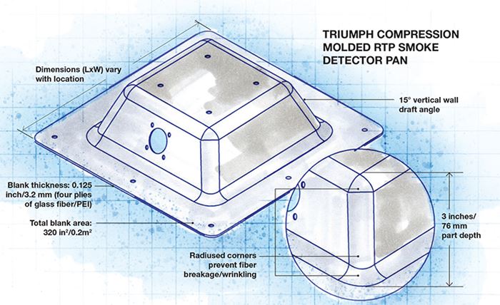
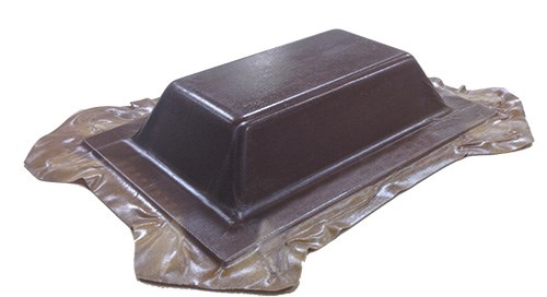
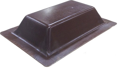
That said, thermoplastic composites, carbon and glass fiber-reinforced, have already won their way into commercial aircraft interiors in a variety of applications — some structural, such as brackets and clips, and some semistructural. An example of the latter, and a testimony to the lengths aircraft OEMs are now willing to go to lightweight their aircraft to enhance fuel economy, is Triumph Composite Systems’ (Spokane, Wash.) continuous fiber-reinforced thermoplastic smoke detector pan. The tray-shaped composite component (see photo, p. 55) is inverted and installed in the aircraft ceiling in many places to provide a mounting space for onboard smoke detectors.
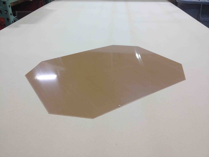
Triumph converted the pan from a hand layup/vacuum bag design. It’s molded from a four-ply 0.045-inch/1.1-mm thick PEI blank supplied by TenCate Advanced Composites USA (Morgan Hill, Calif.) under the Cetex brand. The total surface area of the pan is 320 in2/0.2m2 and it features a hat section that is 3 inches/76 mm deep. Although the pan is glass-reinforced, it illustrates many of the same design lessons Triumph has learned working with continuous carbon fiber.
Housed in a facility once occupied by a unit of The Boeing Co. (Chicago, Ill.), Triumph is a prolific compression molder. Nick Busch, R&D engineer at Triumph, says the company’s smoke pan is a good example of what has become Triumph’s specialty — converting labor-intensive, long cycle-time thermoset-based composite parts to highly automated, short cycle-time thermoplastic-based composites that are manufactured, primarily, via compression molding.
Bigger than it looks
Why go to the trouble for a part so small? The appeal of thermoplastics is understandable: Ease of handling, ease of processability, recyclability, toughness and, notably, no lengthy and expensive cure in an autoclave. Further, aircraft interiors present unique challenges that revolve primarily around fire, smoke and toxicity (FST) mitigation: In case of a crash or onboard fire, aircraft interior components must not only resist burning, but must also self-extinguish after flame source is removed. According to U.S. Federal Aviation Admin. (FAA) standards, most aircraft interior components must not allow a flame burn length of more than 8 inches/203 mm. Further, after removal of the flame source, the flame on the component may not persist for more than 15 seconds.
Compression molding, too, has strong appeal, particularly for aerospace manufacturers who are frustrated by the process inconsistencies inherent in hand-layup, autoclave-based molding processes. Compression molding of thermoplastics typically starts with a preconsolidated blank, usually consisting of several plies of carbon or glass fiber fabric (unidirectional or woven) oriented to meet the mechanical requirements of the application. The reinforcements are infused with a thermoplastic resin, which in aerospace applications is likely to be an engineered material: polyetherimide (PEI), polyphenylene sulfide (PPS), polyetheretherketone (PEEK) or polyetherketoneketone (PEKK).
Although preconsolidated blanks can be manufactured in-house, they also are available from established third parties. Triumph’s pan blanks, for example, are supplied by TenCate Advanced Composites USA, and vary in size, depending on the size of the final part. The molder, then, can order and receive raw materials with a defined and consistent fiber volume fraction and thickness. Additionally, RTP blanks, unlike thermoset prepreg, require no refrigeration and can be stored at room temperature indefinitely.
2-D becomes 3-D
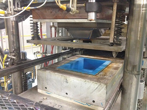
In preparation for molding at Triumph, a blank is usually placed in a frame or attached to a carrier sheet that helps keep the blank properly positioned and oriented in the mold. Frames and carriers also offer cycle-to-cycle positional consistency, a key factor in part repeatability. Next, the blank, on its frame or carrier, is transferred robotically to a preheater (infrared or other heat source) that heats the blank to more than 600°F/315°C, thereby softening it in preparation for molding. The time required for preheating depends on the size and thickness of the blank (usually 0.010 to 0.250 inch or 0.254 mm to 6.35 mm), as well as the resin type, but can take as long as 10 minutes. After preheating, the blank is shuttled into a mold (the mold tools are held at an elevated temperature, typically below the Tg of the material), which immediately closes on the blank and forces the now-soft material to assume the shape of the mold. Robotic handling systems and a prescribed, consistent preheating process also ensure repeatability.
After forming, the part is cooled to harden the matrix and then demolded. Typically, and unlike a thermoset composite part, a thermoplastic blank is designed with sacrificial material on its edges to provide a gripping surface for the positioning frame. This material is removed postmold via machining or trimming to bring the part to its final dimensions. (Also, Busch points out, any porosity problems in thermoplastic parts tend to occur near those edges.) This step can be followed by drilling and/or other finishing steps.
Design challenges
As with every composites manufacturing process, compression molding is ideal for some applications, but not all. Undercuts, sharp angles and complex curvatures are at best difficult if not occasionally impossible. Further, converting an existing part from infusion or a similar process to compression molding, as Triumph does regularly, is more complicated than simply transferring CAD files.
Because compression molding involves the conversion of a flat, effectively 2-D blank into a complex 3-D part, there are, says Triumph’s Busch, certain design rules that must be followed and limitations that must be respected. The rules grow out of the fact that the process induces forces that tend to produce fiber bending, stretching, buckling and wrinkling during the conversion from flat to contoured forms. Many of these principles are illustrated in the smoke pan, which presents several challenges that were met by not readily obvious design solutions.
First, says Busch, with the exception of L- or C-brackets, vertical part walls are strongly discouraged because, as a thermoplastic material cools, it shrinks and “grabs” tooling surfaces. A part with vertical walls thus tends to grip the mold surface against which it was formed, making part removal difficult. The rule of thumb is to design vertical walls with a draft angle of at least 2°. “We like drafted walls better than vertical walls,” he says. As is apparent in the illustration on p. 55, Triumph’s smoke detector pan features a hat section with 15° slopes. Further, says Busch, any hat or pyramid shape like the one on the smoke pan should terminate in a flat surface and not reach a peak.
Second, because continuous glass and carbon fiber tend to wrinkle and buckle when formed around highly concave or convex surfaces, and because such wrinkling compromises the structural integrity of the part, angle changes must be carefully designed and managed. On the smoke pan, for example, a prescribed, curved radius is used to transition fiber and material from one angle to another at the top and the bottom of the hat section, minimizing stress on the fiber and maintaining structural integrity.
“When you go from 2-D to 3-D,” says Busch, “you have to think about what happens when something goes around a corner.”
Triumph’s design software is used to simulate fiber bending as much as possible, but, says Busch, “usually we just rely on trial and error.” As a result, Triumph has developed extensive and proprietary design guidelines that help the company optimize a design for thermoplastic compression molding.
Another factor Triumph has to consider, says Busch, is the processing temperature of the resin. Some thermoplastics require temperatures as much as 100°F/38°C hotter than others, which adds time to the heating cycle. In addition, with so much heat buildup in the part, managing part cooling becomes a more critical concern so as to avoid postmold warpage.
Ultimately, notes Busch, one of the great limiting factors that prevent aerospace parts manufacturers from embracing thermoplastic compression molding is tooling cost. “But,” he says, “you have to look at the full picture to see what the value is.” Such value is built into every stage of the process: High automation, short cycle times and enviable process consistency. Busch says that for the smoke pan, the cost/benefit cutoff for compression molding is about 115 parts/month. Further, Triumph requires only two blank configurations to mold 10 unique part numbers. Most importantly, the smoke detector pan underscores the greatest benefit of conversion from a thermoset layup-based to compression-molded version: a production cycle time savings of 75 percent — a factor any aircraft designer will find not difficult to convert to a dollar value.
Related Content
GKN Aerospace, Joby Aviation sign aerostructures agreement
GKN Aerospace will manufacture thermoplastic composite flight control surfaces for Joby’s all-electric, four-passenger, composites-intensive ride-sharing aircraft.
Read MoreCompPair adds swift prepreg line to HealTech Standard product family
The HealTech Standard product family from CompPair has been expanded with the addition of CS02, a swift prepreg line.
Read MoreComposite resins price change report
CW’s running summary of resin price change announcements from major material suppliers that serve the composites manufacturing industry.
Read MoreVIDEO: One-Piece, OOA Infusion for Aerospace Composites
Tier-1 aerostructures manufacturer Spirit AeroSystems developed an out-of-autoclave (OOA), one-shot resin infusion process to reduce weight, labor and fasteners for a multi-spar aircraft torque box.
Read MoreRead Next
Thermoplastic composites gain leading edge on the A380
Breakthrough manufacturing process produces lightweight, affordable glass-reinforced PPS J-nose on the worlds largest commercial aircraft wing.
Read MoreVIDEO: High-volume processing for fiberglass components
Cannon Ergos, a company specializing in high-ton presses and equipment for composites fabrication and plastics processing, displayed automotive and industrial components at CAMX 2024.
Read MorePlant tour: Daher Shap’in TechCenter and composites production plant, Saint-Aignan-de-Grandlieu, France
Co-located R&D and production advance OOA thermosets, thermoplastics, welding, recycling and digital technologies for faster processing and certification of lighter, more sustainable composites.
Read More

