Designing automation for productivity
Integrated, multistage work cell cuts cost and increases speed, accuracy of hole drilling on the F/A-18 E/F fighter jet's vertical stabilizer.
|
Design Results:
|
Lower part cost is an enduring goal for aerospace composite manufacturers. To achieve that goal, ways must be found to reduce touch labor and speed up or automate repetitive fabrication tasks. For Northrop Grumman Integrated Systems (El Segundo, Calif.), selective automation has become a cornerstone of the company's lean manufacturing concepts for improved productivity at its 1940s-era facility. Major sections of the F/A-18 E/F Super Hornet and the F-35 Joint Strike Fighter (JSF) are assembled at the facility, which has undergone numerous upgrades.
Drilling thousands of holes in airframe assemblies is one of those composite fabrication steps that beg for "a better way." Carbon fibers are notoriously difficult to cut, and the shear stress on the fibers can lead to microcracking or delamination. Moreover, the cutting tools or bits themselves are subject to heavy wear and, if made with carbide or diamond, are expensive as well. Wear must be monitored and tools must be changed out regularly to avoid damage to the part. Hole placement also must be accurate within tight tolerances, and fasteners located on exposed swept surfaces typically have a flushness requirement as well. This mandates that the fastener be countersunk — that is, the fastener head must sit slightly below the part surface, which requires that a precisely shaped, recessed bevel must be cut around the hole to accommodate the fastener head.
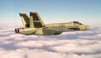
While many airframers still drill holes with hand tools, Northrop has employed automated drilling since 1998. When its original gantry automated drilling system (GADS) became outmoded, Northrop turned to Spanish design and manufacturing firm MTorres (Torres de Elorz, Spain and Santa Ana, Calif.) to develop a technologically advanced system for drilling the F/A-18 E/F's vertical stabilizer. The new vertical automated drilling (VAD) system is a completely automated, turnkey, CNC-controlled cell that drills and countersinks more than 1,000 fastener holes of various diameters in the part, while combining several fabrication processes, previously located in separate areas, into one line for much faster production.
Northrop Grumman's Corey Moore, vice president and leader for the F/A-18 E/F and JSF programs, says, "We're constantly searching for better ways to improve our manufacturing, and this system is just one of a whole new generation of state-of-the-art automation systems out there." Moore reports that the VAD has reduced assembly time by about 35 percent.
Designing automation
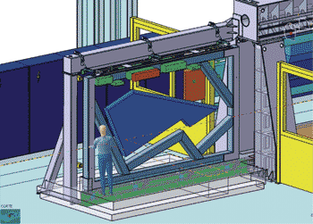
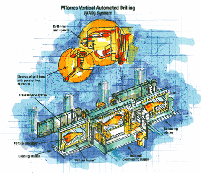
MTorres worked closely with a Northrop team to design the production VAD machine. By combining the work steps needed to produce the vertical stabilizer, a cell with three contiguous and integrated stations was devised: 1) a loading station, where the stabilizer's structural components enter the work cell; 2) the drilling station, where the fastener holes are located, drilled and inspected; and 3) an unloading station, where the completed stabilizer is checked and remaining finishing operations are completed.
The aircraft parts would move through the stations attached to sturdy steel-framed assembly jigs, called "picture frames" because of their rectangular shape. The picture frame is a well-established concept for Northrop Grumman, the company uses similar frames in a number of shapes for assembly of nearly all of its FA-18 E/F parts, including cowlings, fuselage sections, wing boxes and wings. Picture frames would be loaded offline, then moved into place with an overhead crane so that they could be shuttled automatically into the cell, a process taking only a few minutes. A simple transference system was envisioned. It would move the frames between the stations in the machine, using friction wheels connected by electrically driven transmission belts and an upper guide system to hold the top of the picture frame in place. "Centering cones" would position the frame correctly in each station. The machine controller would be programmed to verify closure of all clamps before any work commenced.
According to Northrop's Lance Bryant, director of production engineering and the leader of automation efforts at the facility, the MTorres/Northrop team was able to take advantage of experience gained from the old gantry drilling machine and create a new concept, with the help of a finite element analysis (FEA) model of the drilling head and tool support structure: "The model helped to enhance the tool design and optimize the new system," says Bryant.
The model, created in house by MTorres and used on all of its machine designs, was a key part of the development process for the drilling and countersinking system. It enabled structural calculations, including the rigidity of the head (in x, y and z directions) as well as the support frame; the amount of deflection at the drill tool tip under worst-case loads; and the potential vibration modes and frequencies while drilling. The model also could simulate driving force and dynamic performance, says MTorres USA's general manager David Champa. This enabled an optimum design for the head and the machine's overall support structure for the anticipated loads.
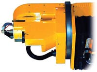
The functional design for the drill head incorporated tilt (A), rotary (B) and feed or drive (W, or quill) axes of motion, in addition to vertical and horizontal (lengthwise) motion along the machine's support frame. The spindle, which holds the actual drill bit, was configured with 119 ft-lb of torque and 17 kW of working power, and features an infinitely variable rotation speed ranging as high as 12,000 rpm. A presser foot on the head was added to apply a uniform and programmable preload on the part from 2.27 kg to 27.2 kg (5 lb to 60 lb). The presser foot then provides a feedback signal to the machine control software, to adjust the W-axis travel distance for the correct hole and countersinking depth. CNC "synchronous action" enables real-time correction of the drill travel, if the part should shift position. Drill depths and diameters are accurate to within ±0.050 mm (±0.002 inch), according to Champa. The machine includes two drilling heads that can drill in unison or each can be programmed to work independently. Each drill head can achieve speeds of 1,016 cm/min (400 inches/min) in the W (drive) axis and up to 3,048 cm/min (1,200 inches/min) along the x-axis, that is, parallel to the work cell, as it moves from hole to hole.
To actually locate the holes to be drilled, the design incorporated a "vision" sensor with two cameras, high-intensity lights and software. During VAD operation, the sensor, supplied by auto-mation and control systems specialist Siemens AG (Munich, Germany), takes thousands of pictures of the part and references the posi-tions of the part's internal structures and skins, via a network of predetermined mea-suring points defined by the model. The CNC machine control software was pro-grammed to execute the measuring step, via the sensor cameras, in milliseconds at an accuracy of within ±0.025 mm (±0.001 inch). A second vision sensor, with two additional cameras, verifies the fastener locations after they are drilled and then documents the drilled holes for reference during quality inspection.
"The automated VAD system helps maintain fastener location and depth consistency even with slight variations in part dimensions, which are inevitable," says Champa. "That's the beauty of automating this type of task."
Bells and whistles
The VAD incorporates some interesting ancillary features, including an automatic tool identification system that "remembers" tool life. A tool changer is located to the side of the drilling head unit so it doesn't interfere with machine motion. As many as to 110 drill bits or countersinking tools can be stored in the changer's magazine. Each tool holder has an attached, pinhead-sized "Balluf" computer chip that stores data on tool type, length, diameter and more, and is integrated into the VAD's CNC controller system. As the drill head finishes a drilling operation and goes to the changer, it can "read" the bits to identify and select the bit with the longest remaining life, to optimize tool life and reduce bit change-out time. The system also can be programmed to perform random tool change-out.
A torque-monitoring device constantly measures and transmits the actual drilling torque to the controller, which allows the system to detect tool wear and breakage. If breakage occurs, the system activates an "escape route" back to the changer, enabling the system to select a new tool, without human intervention. Two separate suction systems with high-efficiency filters collect generated chips and dust to keep the working environment clean. A fire extinguishing system automatically deploys based on a temperature sensor, to minimize any fires from collected dust.
Champa says the system, built in about 12 months, has worked so well for Northrop Grumman that there is a possibility that Northrop will install seven more machines in other existing plants. "A product like the VAD allows a company to modify an existing production line for greater productivity, at a reasonable cost."
Related Content
Bladder-assisted compression molding derivative produces complex, autoclave-quality automotive parts
HP Composites’ AirPower technology enables high-rate CFRP roof production with 50% energy savings for the Maserati MC20.
Read MoreThe basics of composite drawing interpretation
Knowing the fundamentals for reading drawings — including master ply tables, ply definition diagrams and more — lays a foundation for proper composite design evaluation.
Read MoreOptimizing a thermoplastic composite helicopter door hinge
9T Labs used Additive Fusion Technology to iterate CFRTP designs, fully exploit continuous fiber printing and outperform stainless steel and black metal designs in failure load and weight.
Read MoreJeep all-composite roof receivers achieve steel performance at low mass
Ultrashort carbon fiber/PPA replaces steel on rooftop brackets to hold Jeep soft tops, hardtops.
Read MoreRead Next
Plant tour: Daher Shap’in TechCenter and composites production plant, Saint-Aignan-de-Grandlieu, France
Co-located R&D and production advance OOA thermosets, thermoplastics, welding, recycling and digital technologies for faster processing and certification of lighter, more sustainable composites.
Read MoreVIDEO: High-volume processing for fiberglass components
Cannon Ergos, a company specializing in high-ton presses and equipment for composites fabrication and plastics processing, displayed automotive and industrial components at CAMX 2024.
Read MoreDeveloping bonded composite repair for ships, offshore units
Bureau Veritas and industry partners issue guidelines and pave the way for certification via StrengthBond Offshore project.
Read More




.jpg;maxWidth=300;quality=90)


