Designing pressure vessels for seawater desalination plants
Safe high-pressure service challenges manufacturers of composite pressure vessels.
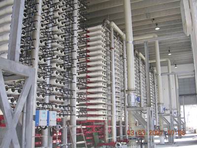
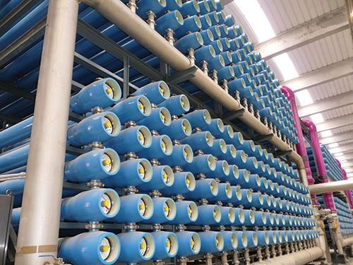
Seawater reverse osmosis (SWRO) desalination depends on membrane systems that serially cleanse water piped onshore from the ocean (see “Composites slake the world's thirst” and “Designing pressure vessels for seawater desalination plants”). These membranes must be encased in membrane housings. Filament-wound fiberglass pressure vessels are used almost exclusively for this purpose today, in quantities of as many as 6,000 per desalination plant. The Freedonia Group (Cleveland, Ohio, U.S.) predicts demand for SWRO housings and related equipment will increase 6.9% per year.
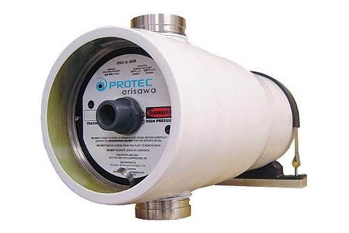
In the vanguard of this trend is Protec-Arisawa (Tokyo, Japan), which has filament wound SWRO vessels for desalination plants all over the world. It also operates in Spain and, notably, in Southern California, where extended droughts and “water fights” centered on environmental issues have taken their toll on the drinkable water supply, prompting San Diego County officials to authorize construction of a desalination plant. In mid-2013, Protec-Arisawa America (Vista, Calif.) received a SWRO pressure vessel contract for this plant. Proposed and developed by Poseidon Resources (Stamford, Conn.), it is now under construction by Kiewit Shea Desalination (Carlsbad, Calif.) and Kadima, Israel-based subcontractor IDE Technologies, a few miles away in ocean-side Carlsbad (see “Seawater Desalination plant approved for Southern California,”). When it is completed in 2015, it will be the largest desalination operation in the Western Hemisphere.
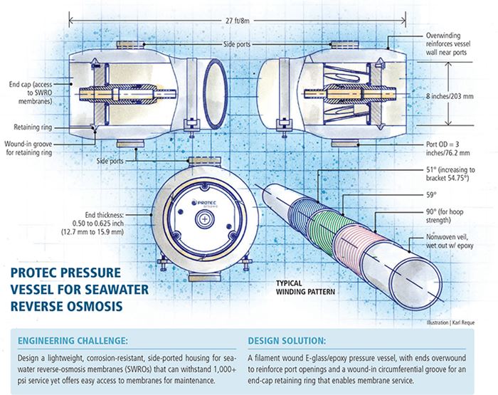
According to Protec-Arisawa America product manager Richard Chmielewski, the IDE Technologies order calls for 2,016 BPV-8-1200-MSP vessels (8-inch/203-mm diameter) rated at 1,200 psi/82.77 bar (see drawing, p. 55), plus 38 PRO-8-600 (600 psi/41.37 bar) and 182 PRO-8-450 (450 psi/31 bar) vessels. Each of these ~27-ft/8m long housings will contain eight standard 8-inch/203-mm diameter, 40-inch/1,016-mm long RO membranes. Today, the job is almost routine: Protec-Arisawa has, at this writing, more than 60,000 vessels in nearly 200 facilities. But it wasn’t always so.
From steel to composites
In the mid-1960s, SWRO’s early days, the focus was on the success or failure of the RO membranes, but it soon became apparent that the housings — then of welded carbon steel pipe — also required attention. “There were corrosion issues immediately,” recalls Doug Eisberg, director of business development for Avista Technologies (San Marcos, Calif.) and an SWRO industry pioneer. “There were issues with weight,” he adds, “and there were problems with the inside surface quality of the pipe.” To ensure a tight seal on the vessel end-closures and the brine seals that fix membranes to the pressure vessel, a smooth, consistent inner surface is critical. The inner surface of steel pipe was neither.
By 1978, SWRO designers had turned to filament-wound fiberglass pipe. Although this immediately resolved the corrosion and weight issues and yielded a smooth inner surface, it took some time to develop designs that could handle the pressures. “At 600 psi,” Eisberg recalls, “the end-closures began flying off the vessels and going through the buildings like cannons. Very destructive. We had this great material, now, but the question became, What are we going to do to keep it safe?”
Code-compliant composites
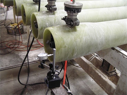
In the mid-1980s, the industry sought safety guidance in the Boiler and Pressure Vessel Code of the American Society of Mechanical Engineers (ASME). Section X, Fiber Reinforced Plastic Pressure Vessels, establishes conditions that must be met, no matter how the composite vessel is configured. It calls for hydrostatic tests that cycle the vessel from zero to design pressure 100,000 times, at 150°F/65.5°C. The same vessel is then pressurized hydrostatically to a safety factor of six times the design pressure. With a target for safe service, pressure vessel winders were able to develop E-glass/epoxy architectures and ply schedules specifically designed to pass the Section X tests. (E-glass roving has demonstrated better performance in cyclic fatigue testing than corrosion-resistant, or E-CR, glass.)
Protec’s Carlsbad order specifies code-stamped vessels, and Chmielewski says that’s now no problem. By the end of the 1980s, most SWRO housing manufacturers, Protec-Arisawa among them, considered them the standard. “We design all our vessels to code,” he explains. If a customer orders code-stamped vessels, an ASME inspector is called in to verify the manufacturing process and testing for the stamp, but if a code stamp is not required, Protec calls in an independent inspector for verification anyway. And Protec goes further: “We maintain all the material certifications, and we have a document that travels with each vessel that stipulates which winder it was made on, what batch or lot of glass and resin, the curing temperature logs, and so on.”
Critical point loads
A troubling design issue was how best to handle stress concentrations in the vessel ends, which are weakened by the various attachment techniques for end-closures and side-port fittings. At first, all filament-wound vessels had high-pressure feed and concentrate ports for the seawater at each end of the vessel. However, side ports were common in metal housings because they permitted unobstructed membrane access, and SWRO plant operators wanted them on composite housings, because they eliminate the need to disconnect the high-pressure feedwater piping to service the membranes and offer a simpler path for feedwater delivery to multiple RO systems.
Cutting side-port holes through the composite vessel wall, however, compromised vessel strength. In the late 1980s, Eisberg led a team at Codeline (now Codeline-Pentair, Minneapolis, Minn.) to address this risk. After a long development cycle, today’s successful designs for 1,000+ psi service typically call for vessel ends to be overwound to build up the required strength, using localized filament winding (Protec’s method) or reinforced by bidirectional mats, resulting in a dog bone-shaped vessel. For the end-closures, Protec either winds-in a metallic retaining ring attachment on the mandrel or overwinds a removable groove former for integrally winding in the grooves. Retaining rings have finger pulls to simplify end-cap removal.
Realizing the design
Today, Protec uses standard SolidWorks finite element analysis software from Dassault Systèmes SolidWorks Corp. (Waltham, Mass.), customized to design the filament wound shell and the head assembly for end-closure. Vessels are wound on equipment supplied by Entec Composite Machines (now Engineering Technical Corp., Salt Lake City, Utah), a subsidiary of Zoltek Inc. (St. Louis, Mo.), over outsourced, chrome-plated carbon steel mandrels that are ground to Protec’s specifications.
Fabrication typically begins with application of a nonwoven polyester or other synthetic veil over the mandrel. The veil protects the inside surface so it can handle cycling test requirements. The veil is usually wet out with toughened epoxy resin, says Eisberg, noting that some manufacturers B-stage this layer before winding begins. In the resin bath, a toughened epoxy specially formulated for corrosion resistance, durability and dimensional stability is used. The goal is minimum 75 percent glass content.
Although Protec’s fiber architecture and ply schedules are proprietary, Avista’s Eisberg says there are general guidelines for meeting ASME requirements. Based on his 30+ years in the industry, fabrication follows a familiar pattern: When the veil is in place, he says, winding typically starts with a circumferential layer for hoop strength and to reinforce a smooth and consistent inside surface. This is generally followed by layers of high angle winding, up to 59°, for axial reinforcement and to strengthen the ends of the vessel for attachments and cutouts. After that, Eisberg continues, the structural layers are wound, starting around 51°, in bandwidths between 2.5 and 5 inches (63.5 mm and 127 mm). As the diameter of the vessel increases on the mandrel, the wind angle is slowly increased to adjust to the new diameter. Eisberg explains that the goal is to bracket (that is, wind with an equal number of passes at angles greater and less than) 54.75° because “this is the ultimate 2:1 wind angle for this type of product.” Nominal wall thickness is typically 0.50 inch to 0.625 inch (12.7 mm to 15.9 mm) on the overwound ends for vessels intended for seawater service.
When winding is complete, Protec transfers the mandrel and vessel to an oven, where the part rotates while it is cured. “To verify cure, we weigh every vessel, do a Barcol hardness test and take a sampling of the glass/resin ratio,” Chmielewski says.
Protec then precision mills holes for the side ports and machines and installs those fixtures. For the Carlsbad job, IDE specified Sandvik 254 SMO high-alloy super-austenitic stainless steel drill tools supplied by Sandvik AB (Sandviken, Sweden) for 3-inch/76.2-mm side port fixtures. Protec then tests one vessel assembly of each model/size to the ASME X standard, with end-closures installed and mechanical plugs in the side ports. Chmielewski notes that Protec can fabricate about 100 8-inch diameter, 27-ft long vessels per day.
Danger in high demand
For 25 years, ASME Code Section X has been considered the minimum safety standard. Although the increase in desalination plant construction is welcome, industry leaders say low-cost vessels that have not been rigorously pressure tested are entering the market and could, again, damage plants and inflict injuries if they fail. “If this were to happen,” says Eisberg, “it would negatively affect the entire desalination market.” He warns that the industry must remember its past or repeat it.
Related Content
Polar Technology develops innovative solutions for hydrogen storage
Conformable “Hydrogen in a Box” prototype for compressed gas storage has been tested to 350 and 700 bar, liquid hydrogen storage is being evaluated.
Read MoreNovel composite technology replaces welded joints in tubular structures
The Tree Composites TC-joint replaces traditional welding in jacket foundations for offshore wind turbine generator applications, advancing the world’s quest for fast, sustainable energy deployment.
Read MoreMingYang reveals 18-MW offshore wind turbine model with 140-meter-long blades
The Chinese wind turbine manufacturer surpasses its 16-MW platform, optimizes wind farm construction costs for 1-GW wind farms.
Read MoreDrag-based wind turbine design for higher energy capture
Claiming significantly higher power generation capacity than traditional blades, Xenecore aims to scale up its current monocoque, fan-shaped wind blades, made via compression molded carbon fiber/epoxy with I-beam ribs and microsphere structural foam.
Read MoreRead Next
Composites slake the world's thirst
As the global thirst for drinkable water increases, the composites industry is drinking in the tremendous possibilities in seawater desalination.
Read MorePipes vs. vessels
CT editor-in-chief Jeff Sloan notes the value of composite pressure vessel standards in the growing market for seawater desalination.
Read MoreVIDEO: High-volume processing for fiberglass components
Cannon Ergos, a company specializing in high-ton presses and equipment for composites fabrication and plastics processing, displayed automotive and industrial components at CAMX 2024.
Read More


.jpg;maxWidth=300;quality=90)


