Share
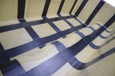
One aspect of HRC’s large study evaluated the performance of chopped carbon fiber-reinforced SMC (CF-SMC) and chopped glass fiber-reinforced SMC (GF-SMC), with and without unidirectional (UD) CF prepreg (CF-prepreg) reinforcements along the main load paths. Photo Credit, all images: HRC Group
As detailed in the February 2022 Focus on Design, “SMC material configurations tailored to automotive battery enclosure design,” and online side bar “Hybrid battery cover: CAE approach,” an international team from China and Europe has been working on a multivariant feasibility study to develop a new electric vehicle (EV) battery system. Led by HRC Group (Changshu, China), one aspect of the study was design and production of a sheet molding compound (SMC) cover to house either two or four battery modules. HRC researchers designed the study to provide customers with a range of options regarding cost, weight and mechanical performance. Along the way, the team made some interesting choices about materials and processing. What follows is a conversation between Timo Huber, vice president of HRC’s Advanced Composite Technology Center (ACTC), and CW contributor Peggy Malnati discussing these decisions.
Malnati: Why partially cure the prepreg strips rather than mold prepreg and SMC in one slightly longer molding cycle?
Huber: In principle, this case study could transfer to many applications — some of which might use full automation and some which might be only semi-automated. We felt it was better to have a preform in a stable condition so it could be handled robotically, and that would require a stiffer material that was partially cured before the SMC stack was placed in the tool. This was important since we didn’t want the prepreg inlay to shift out of position during material insertion or during molding of the SMC, which will flow. If we had used a weaker material, the prepreg would have been more likely to move.
Malnati: If you lay the SMC stack on top of the prepreg strips, how do you keep the B-staged prepreg from moving during molding?
Huber: First, the work that Simutence
The team explored the performance change of co-molding a lattice of B-staged carbon fiber-reinforced prepreg with CF-SMC and GF-SMC (the prepreg matrix was matched to the SMC matrix in each case).
Malnati: Why not use a piece of fabric instead of cutting out and laying up a lattice of prepreg strips? Was this to keep cost and weight down? And did you consider unidirectional (UD) fiberglass or just carbon fiber for the prepreg?
Huber: Placing a fabric in the tool and back-molding it with SMC is actually easier than what we did. However, simulations showed the best performance was achieved by locally reinforcing the main load paths, so we chose that option. If we had been molding a flat plate, fabric would have been better, but our cover has a lot of geometry and deepdraw sections, which would have been difficult to fill with SMC if it sat on fabric instead of a pattern of strips. And we did consider fiberglass for our prepreg. It does offer better impact at lower cost, although at slightly higher weight. However, carbon fiber prepreg has the highest stiffness and strength at the lowest weight, so our strategy was to use glass reinforcement in big areas of the part and continuous carbon fiber only where we needed it.
Malnati: Why were different resin systems used for the CF-SMC (epoxy/acrylate) and the GF-SMC (unsaturated polyester/urethane)?
Huber: We tested far more materials than what we ended up using to mold actual parts, but some of those materials were still in the development phase and not yet commercial. Where possible, we felt it was better to work with materials that were readily available in case a customer wanted to start producing parts relatively quickly.
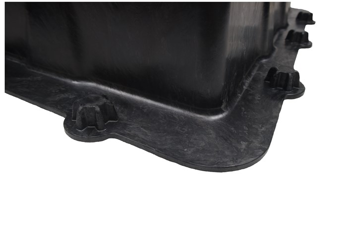
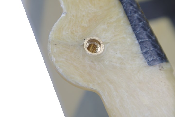
To facilitate eventual assembly of the cover to its base/tray, the team insert molded 10 knurled screw inserts.
Malnati: What can you tell us about the no-flow resin system that AOC developed for the prepreg? And did you do any formal peel tests to ensure you have a good bond between the prepreg strips and the SMC?
Huber: AOC has developed unique technology within its Daron family that allows for tuning of flow during molding. They use two different polymer backbones to formulate urethane-thickened resins with different maturation levels. Daron 8151 gives good, flowable SMC — with either glass or carbon fiber — at typical molding conditions of 100 bar at 150°C. Flow can easily be fine-tuned to meet the requirements of even very complex mold cavities. They also have a urethane-thickened hybrid resin called Daron 8300 NF, which does not flow under molding conditions. This allows processors to form components with regions of unidirectional long fibers that can absorb stresses present in the load path of a product — or, as AOC calls it, “Strength where you need it.” Both grades have the same cure chemistry, which results in covalent chemical bonds and leads to ideal adhesion between Daron 8151 and Daron NF. In our case, that’s the SMC and the prepreg[PM1] . While we didn’t cut out specimens and run peel tests, we did section some parts and can see that we have excellent chemical bonding with no delamination. This is what we’d expect because the base resins are the same for both prepreg and SMC in each case.
Malnati: Would you use the same materials for the base/tray that you used for the cover?
Huber: The baseplate would likely have different materials or at least a different construction — most likely a sandwich panel — because it needs to hold cooling channels to help prevent the batteries from overheating. We’ve been working on this part in a parallel study and have been working on an innovative approach, but it’s not yet finalized.
Malnati: Speaking of other materials, you mentioned that future work would involve evaluating options to flame retard and electromagnetically shield the cover. How is that work going? Have you considered using foils or sheets of aluminum, or would you try to shielding with additives?
Huber: Co-molding a metal foil wouldn’t work as it would always be destroyed during the forming process. And while the state-of-the-art approach is either to use an aluminum blanket or to use a shielding paint on the part, such steps are costly. We have been looking at options for creating intrinsic shielding. Our investigations are still ongoing, although we’ve already concluded that we will always need carbon fiber inside the SMC. We’ve already tried and ruled out carbon black, carbon nanotubes, graphene and combinations of these. Additives always have a limitation because, as the concentration increases, they can cause dramatic changes in mechanicals and lead to brittleness. However, our biggest challenge at this point is lack of information. Shielding is a complex problem and we don’t know what level of shielding we’re going to need or whether it will be measured on individual components or the entire battery pack. We need to wait for OEMs, battery manufacturers and others to determine what performance is needed and then find an appropriate solution.
Malnati: Did your team face any challenges designing and building the tool? Was there any concern about molding any of the details?
Huber: We had some challenges owing to the design of the cover. For example, the part is not symmetric. We have a high core on the male side and that leads to a disbalance of material when SMC is placed in the tool. If we weren’t careful, and our presses weren’t fitted with good parallelism control, that could lead to high loads on the transversal of the mold, which could have caused the core to move. We have a lot of experience molding SMC and know you can’t predict with 100% accuracy where every piece of material will go every time you mold the material. Hence, we’ve learned to always make sure our tools are stiff enough. So, for this tool, we designed it with very stiff edges using a frame concept that helps guide and stabilize all four sides of the tool during press opening and closing.
Malnati: How big is this part and how big a press did you need to mold it?
Huber: The cover is 912 millimeters in length, 564 millimeters wide and 252 millimeters at the greatest height. We molded parts in two presses: one with 3,200 tonnes clamping pressure and another with 2,500 tonnes, but we didn’t come close to using full pressure. We molded the parts with around 200-300 bar (20-30 MPa) forming pressure.
Malnati: Is any post-mold trimming, punching or other cutting required?
Huber: If you look at the design, you can see there are a number of windows/holes that have to be produced post-process because otherwise you end up with a very complex mold and you create knitlines that can be weaker than the surrounding material where flow fronts come back together.
Malnati: Based on what you learned during this study, what changes would you make going forward with an actual customer program?
Huber: Actually, we wouldn’t make major changes but we would make some minor adaptations. We already have a complex tool, material and geometry to produce these battery covers and we consider this study project very successful, as it opened up a lot of options for customers wanting to bring the technology to series applications.
Malnati: Is there anything you would tell a customer about the materials you used or the process you developed that would cause any future program to be done slightly differently?
Huber: For sure they would want to use automation. And there would be specific questions based on the needs of the program. However, we feel that, in principle, this approach works well and allows us to offer customers many options, including SMC formulation in-house on our own compounding line or by using materials our partners AOC and Mitsubishi already have developed. We can literally support a customer from concept through to production.
Related Content
Improving carbon fiber SMC simulation for aerospace parts
Simutence and Engenuity demonstrate a virtual process chain enabling evaluation of process-induced fiber orientations for improved structural simulation and failure load prediction of a composite wing rib.
Read MoreHybrid process marries continuous, discontinuous composites design
9T Labs and Purdue applied Additive Fusion Technology to engineer a performance- and cost-competitive aircraft bin pin bracket made from compression-molded continuous and discontinuous CFRTP.
Read MoreGuidance for the thermoforming process
A briefing on some of the common foam core material types, forming methods and tooling requirements.
Read MoreActive core molding: A new way to make composite parts
Koridion expandable material is combined with induction-heated molds to make high-quality, complex-shaped parts in minutes with 40% less material and 90% less energy, unlocking new possibilities in design and production.
Read MoreRead Next
Plant tour: Daher Shap’in TechCenter and composites production plant, Saint-Aignan-de-Grandlieu, France
Co-located R&D and production advance OOA thermosets, thermoplastics, welding, recycling and digital technologies for faster processing and certification of lighter, more sustainable composites.
Read More“Structured air” TPS safeguards composite structures
Powered by an 85% air/15% pure polyimide aerogel, Blueshift’s novel material system protects structures during transient thermal events from -200°C to beyond 2400°C for rockets, battery boxes and more.
Read MoreAll-recycled, needle-punched nonwoven CFRP slashes carbon footprint of Formula 2 seat
Dallara and Tenowo collaborate to produce a race-ready Formula 2 seat using recycled carbon fiber, reducing CO2 emissions by 97.5% compared to virgin materials.
Read More

.jpg;width=70;height=70;mode=crop)


