Material deformation and recovery test methods
Dr. Donald F. Adams (Wyoming Test Fixtures Inc., Salt Lake City, Utah) reviews ways and means to quantify composite material deformation and recovery.
A concern in some practical applications of materials, including composites, is their ability to resist permanent deformation with time under load; to sustain a load when they are deformed by a fixed amount; and/or to recover their initial dimensions after the load is removed. These three behaviors are associated, respectively, with material creep, relaxation and recovery.
Most composite materials, including polymer-matrix composites, do not exhibit these time-dependent behaviors to a significant extent. Even if the matrix material permanently deforms, the fiber reinforcement typically will not and, therefore, provides the constraint sufficient to maintain dimensional stability. Nevertheless, there are material configurations, loading conditions and service environments in which dimensional changes, favorable or otherwise, can arise. For example, a component could creep during long-term loading in a hot, wet environment and no longer perform its function. A bolted joint could loosen with time as material relaxation decreases the clamping force under the bolt head. Or a dent in a composite auto body panel could slowly recover its original shape.
Standardized tests have been developed to characterize these behaviors. Although they were initially developed for materials other than composites, the tests have since been adopted, as appropriate, for use with composites. One example is the so-called Compression Set, as governed by ASTM D3951. This standard includes both Method A-creep and Method B-recovery. The desired loading can be and sometimes is supplied simply by stacking dead weights on the specimen. But the need to expose specimens to loads for long periods of time under various circumstances has made simple fixturing dedicated to the purpose the usual choice.
A spring-loaded frame is used to apply the creep load of Method A. Either the spring is calibrated such that a given deflection is known to produce a given force, or an external testing machine is used to apply the desired force to the spring (and specimen). In the latter case, the spring is held in the compressed state and the apparatus can be removed from the testing machine to free it for other uses. Because it is much more stable, portable and compact than dead weights, the spring-loaded frame is easily moved in and out of various temperature, humidity and ultraviolet chambers, as well as salt spray and water and other liquid baths, to simulate variations in actual use environments while specimen deformation is monitored as a function of exposure time.
Although ASTM D395 includes only compressive creep, the same general procedures can be used to measure tensile creep. A suitable apparatus for this purpose is described in ASTM D22942.
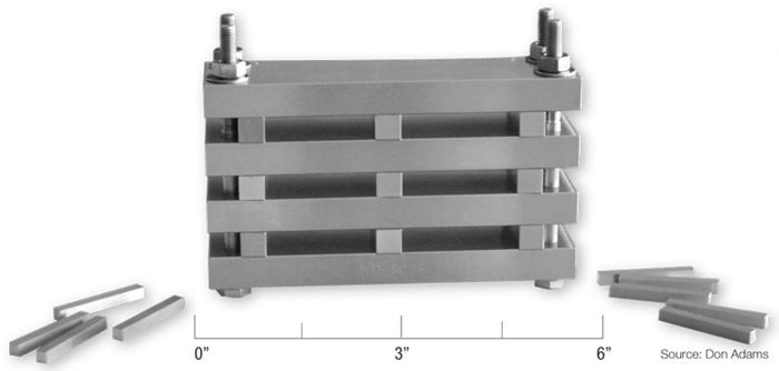
To determine recovery, tests are performed by clamping disk-shaped specimens between rigid plates for a given period of time and then, after the clamping force is released, monitoring the recovery rate. A typical fixture for this purpose is shown in Fig. 1, assembled but without specimens installed. The bolts are loosened sufficiently, and one or more specimens, depending on their size and the total number of specimens to be tested, are placed in each opening. Then the bolts are tightened until the plates contact the spacer bars, compressing the specimens a fixed amount in the process. The amount of specimen compression is dictated by the specimen thickness relative to that of the spacers. For example, in ASTM D395, which was originally developed for rubbers, the specified amount of initial compressive deformation is 25 percent.
For polymers and composites, initial deformation can be whatever is appropriate for the application, perhaps only a few percent, and is controlled by the thickness of the spacer bars. After a specified length of time (typically less than 100 hours), the specimens are removed from the fixture and the rate of recovery of specimen thickness is monitored. The small, portable recovery test fixtures also can be moved readily in and out of exposure environments.
Note that although ASTM D395 does not include relaxation (load drop-off), a load cell can be used in conjunction with the bolts while the specimen is in the fixture to monitor the clamping-force decrease as a function of time and the recovery rate after the specimen is removed.
Also, ASTM D395 considers only compressive loading effects. But ASTM D13293 is an example of a standard that addresses recovery following tensile loading. A typical apparatus, capable of testing up to six tensile specimens at one time, is presented in Fig. 2. Like the fixtures mentioned earlier, this easily transportable apparatus can be placed in any exposure environment. As shown, the specimens have enlarged ends. The ends provide a large surface for gripping and define the specimen’s gage length (that is, the length of reduced cross-sectional area where most of the deformation will occur). Although in principle the gage length could be established by the testing agent, ASTM D1329 does specify three standard gage lengths: 25, 38 or 51 mm (1.0, 1.5 or 2.0 inches). One end of each specimen is secured under a clamping bar, and the other end is held in its own individual clamp, as shown. Each specimen is then manually elongated to the length desired as the clamp is pulled and then anchored to the base plate.
ASTM D1329, in particular, is designed to determine the temperature-dependent amount of recovery (retraction). The specimen is monitored while it is slowly warmed to room temperature after being held in an elongated state while exposed to a very low temperature. But the same general procedure can be used to monitor recovery when the specimen is cooled to room temperature after exposure to elevated temperature under deformation, or after the specimen absorbs solvents or other fluids under deformation.
Expect to see simple creep, relaxation and recovery fixtures used increasingly as composite materials continue to expand into new application areas that require knowledge of these material properties. Fixtures and test procedures will be developed and new standards will be written specifically for composites.
References
1ASTM D395-03 (2008), “Standard Test Methods for Rubber Property – Compression Set,” ASTM International (W. Conshohocken, Pa.), reapproved 2008.
2ASTM D2294-96 (2008), “Standard Test Method for Creep Properties of Adhesives in Shear by Tension Loading (Metal-to-Metal),” ASTM International (W. Conshohocken, Pa.), reapproved 2008.
3ASTM D1329-08, “Standard Test Method for Evaluating Rubber Property – Retraction at Lower Temperatures (TR Test),” ASTM International (W. Conshohocken, Pa.), revised 2008.
Related Content
Numerical tool with mean stress correction demonstrated for fatigue life estimation of thermoplastic composites
To aid design of fatigue-resistant structures, Econ Engineering has developed an algorithm to evaluate ply-based cyclic stiffness degradation combined with an FE failure check, validated for a CF/PAEK pressure vessel.
Read MoreNotched testing of sandwich composites: The sandwich open-hole flexure test
A second new test method has been standardized by ASTM for determining notch sensitivity of sandwich composites.
Read MoreInterlaminar tensile testing of composites: An update
New test method developments for measuring interlaminar tensile strength address difficulties associated with the ASTM D6415 curved beam flexure and ASTM D7291 flatwise tensile tests.
Read MoreMeasuring ply-wise deformation during consolidation using embedded sensors
Strip-type shape sensor method claims real-time measurement of ply-wise deformation.
Read MoreRead Next
VIDEO: High-volume processing for fiberglass components
Cannon Ergos, a company specializing in high-ton presses and equipment for composites fabrication and plastics processing, displayed automotive and industrial components at CAMX 2024.
Read MorePlant tour: Daher Shap’in TechCenter and composites production plant, Saint-Aignan-de-Grandlieu, France
Co-located R&D and production advance OOA thermosets, thermoplastics, welding, recycling and digital technologies for faster processing and certification of lighter, more sustainable composites.
Read MoreDeveloping bonded composite repair for ships, offshore units
Bureau Veritas and industry partners issue guidelines and pave the way for certification via StrengthBond Offshore project.
Read More


