Optimum unidirectional compression testing of composites
Dr. Daniel O. Adams, a professor of mechanical engineering, the director of the Composite Mechanics Laboratory at the University of Utah, and VP of Wyoming Test Fixtures Inc. (Salt Lake City, UT, US) discusses the complex relationship between composite tensile and compressive properties, why that makes it necessary to perform both tension and compression testing, and how best to perform the latter.
Unlike metals and plastics, for which tensile and compressive properties are the same or very similar, unidirectional composites exhibit significantly different mechanical properties, such that both tension and compression testing must be performed.
The relationship between composite tensile and compressive properties is complex. The tensile and compressive modulus of elasticity of unidirectional composites in the fiber direction, E1, are similar, but differences of 10% or more are commonly observed for carbon/epoxy composites, with the compressive modulus typically lower. The reason for these differences is not well understood. More importantly, however, the tensile and compressive strengths of unidirectional composites in the fiber direction differ greatly, with the compressive strength often significantly lower than the tensile strength. This strength difference results from the different failure modes that occur for each: fiber tensile failure under tension loading vs. fiber micro-buckling under compression loading. This lower compressive strength has important consequences for design, especially in applications that involve flexural loading, in which equal magnitudes of tensile and compressive stress are produced. Unfortunately, it’s impossible to predict the unidirectional compressive strength of composites based on fiber and matrix properties, even when tensile strength is known. Thus, compression testing typically is performed in addition to tension testing, and compressive strength is widely considered the more critical property.
Measuring compressive strength of unidirectional composites is among the most difficult tasks in composites testing. In my January 2015 column (see "Tensile testing of composites: Simple in concept, difficult in practice," under "Editor's Picks," at top right), I summarized the difficulties associated with obtaining the tensile strength of unidirectional composites. These stem from the need to introduce a relatively large load into the specimen and produce failure in the central gage section before failure occurs elsewhere. The same is true for compression testing, and potential specimen buckling/bending make compression testing even more difficult.
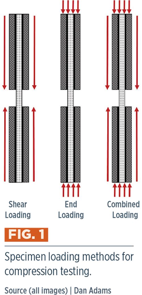
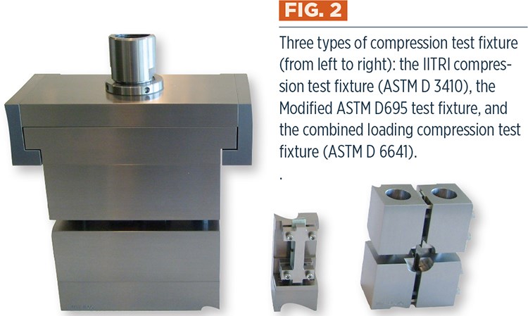
To get the most out of the compression test, we must first select a test method. The primary difference among the commonly used methods is the manner in which compressive load is introduced into the specimen (Fig. 1): through shear loading of the tabbed specimen surfaces, through direct compression loading of the specimen ends, or a combination of the two. Regardless of the loading method used, however, tabbed specimens are typically required to achieve the desired results. Typically glass fabric/epoxy printed circuit board material is used for tabbing compression specimens, because it is readily available at low cost, has low stiffness but high strength and can be machined in the same manner as the tested composite material. The most commonly used shear-loaded compression test method is ASTM D 34101. Its test fixture (Fig. 2) includes flat wedge grips that are bolted onto the tabbed surfaces of the specimen, with the assembly placed into mating cavities with wedge-shaped spacers. Alignment rods and linear bearings provide the required alignment between fixture halves. Upon loading, wedge-action gripping is produced in a manner similar to mechanical wedge grips used in tensile testing. For unidirectional composites, the test method specifies a 13-mm wide specimen that is 140 mm long with a 13-mm gage length between the tabs. However, greater specimen widths and gage lengths are permissible, if desired. Although popular in the 1990s, ASTM D 3410 is used less frequently now, due to the large fixture’s high cost and the development of other more popular test methods.
End loading of the specimens is another option, but tabs are required here as well to achieve a suitable compression failure in the gage section prior to crushing or splaying at the specimen ends. Additionally, lateral supports are needed to prevent buckling during loading. The most popular end-loaded compression test method is the Modified ASTM D 695 test method (Fig. 2). There is actually no ASTM standard governing this method, but it is defined in the SACMA Recommended Test Method SRM 1R-942. ASTM D 695 specifies a shorter 4.7-mm gage length. This reduces the risk of specimen buckling for a given specimen thickness. But there’s a downside: this gage length is too short to permit the use of strain gages or extensometers and, therefore, a separate set of untabbed specimens must be tested for elastic modulus determination.
The third method of loading combines both shear loading and end loading. The Combined Loading Compression (CLC) test method, ASTM D 66413, was standardized by ASTM in 2001, and has become the most commonly used compression test method for composites. Its test fixture (Fig. 2) consists of four steel blocks with specimen gripping surfaces coated with tungsten carbide particles. The upper and lower pairs of fixture blocks are bolted to the tabbed specimen, and the assembly is loaded between flat platens. The amount of shear loading is controlled by the torque applied to the bolts that connect the fixture blocks, with a goal of providing sufficient shear loading to avoid crushing at the specimen ends. The specimen dimensions are the same as those specified in ASTM D 3410, although specimen widths up to 30 mm can be accommodated. Advantages of the CLC test method include the relatively small, simple and inexpensive test fixture and the potential to obtain compressive strength test results with less data scatter — a benefit of combined shear and end loading.
Regardless of which test method is selected, the most important consideration is proper specimen design. As in tensile testing, relatively thin specimens are of interest, and bonded tabs are required. Unlike tensile testing, however, the use of a shallow tab taper angle leading into the gage section isn’t possible due to the risk of buckling. In general, a thicker specimen and shorter test section are needed to prevent specimen buckling prior to compressive failure. Typically, the shortest practical test section length is selected, and the required minimum specimen thickness to prevent buckling is determined. The two popular ASTM test methods for compression testing of composites, ASTM D 3410 and D 6641, provide an equation for calculating the required specimen thickness, h, to prevent bucking of an orthotropic specimen of rectangular cross section, which can be written as

where lg is the specimen gage length, Ex is the axial modulus of elasticity in the loading direction, Gxz is the interlaminar shear modulus, and σcu is the estimated compressive strength of the specimen. Without having performed tests, values for these three material properties may not be known and, thus, will need to be estimated. Although it might be tempting to neglect the last term in the denominator, 1.2/Gxz, especially when a value of Gxz is not readily available, doing so will result in a significant underprediction of the required specimen thickness and the likelihood of specimen buckling. Since this formula estimates the minimum specimen thickness to prevent buckling, it’s recommended to increase the specimen thickness an additional 10-20% above the calculated value.
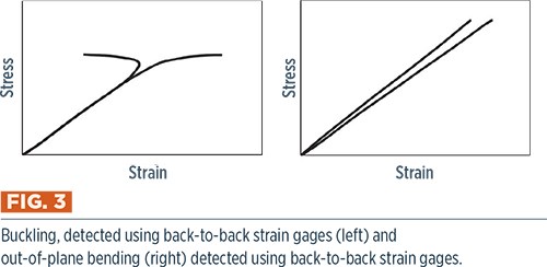
Additionally, because buckling cannot be detected visually during testing or from failed specimens, the use of back-to-back strain gages on the specimen faces during testing is required to determine that buckling is not occurring. Buckling results in a sudden divergence of the strains on the specimen faces (Fig. 3), and can significantly reduce the measured compressive strength. Therefore, it is recommended that back-to-back strain gages be used on the initial set of compression tests and that the strains be analyzed before proceeding with additional testing.
Similar to buckling, out-of-plane bending is of concern when compression testing because the variation of strains and stresses across the specimen thickness can lead to reductions in measured compression strength. Bending is commonly traced to problems in specimen fabrication and machining that result in thickness variations. However, bending also can be the result of misalignment in the test fixture or even the testing machine. Similar to buckling, specimen bending may be detected using back-to-back strain gages during testing. However, bending produces a difference in the slopes of the stress vs. strain diagrams from the two gages throughout the test (Fig. 3) rather than a sudden divergence. Let’s note, here, that the ASTM standards mentioned above limit bending to less than 10% during the entire test. Interestingly, research results4 suggest that higher levels of bending (up to 30%) do not significantly reduce compressive strength. Thus, although efforts must be made to minimize misalignments that lead to out-of-plane bending, buckling remains the greater concern.
References
1ASTM D3410/D3410M-03(2008), “Standard Test Method for Compressive Properties of Polymer Matrix Composite Materials with Unsupported Gage Section by Shear Loading,” ASTM International (W. Conshohocken, PA, US), reapproved 2008 (first issued in 1975).
2SACMA Recommended Method SRM 1R-94, “Compressive Properties of Oriented Fiber-Resin Composites,” Suppliers of Advanced Composite Materials Assn. (Arlington, VA, US), 1994.
3ASTM D6641/D6641M-09, “Standard Test Method for Compressive Properties of Polymer Matrix Composite Materials Using a Combined Loading Compression (CLC) Test Fixture,” ASTM International (W. Conshohocken, PA,US), 2009 (first issued in 2001).
4P.M. Wegner and D.F. Adams, “Verification of the Combined Load Compression (CLC) Test Method,” Final Report DOT/FAA/AR-00/26, Federal Aviation Admin. (Washington, DC, US), August 2000.
Related Content
ASCEND program update: Designing next-gen, high-rate auto and aerospace composites
GKN Aerospace, McLaren Automotive and U.K.-based partners share goals and progress aiming at high-rate, Industry 4.0-enabled, sustainable materials and processes.
Read MoreActive core molding: A new way to make composite parts
Koridion expandable material is combined with induction-heated molds to make high-quality, complex-shaped parts in minutes with 40% less material and 90% less energy, unlocking new possibilities in design and production.
Read MoreATLAM combines composite tape laying, large-scale thermoplastic 3D printing in one printhead
CEAD, GKN Aerospace Deutschland and TU Munich enable additive manufacturing of large composite tools and parts with low CTE and high mechanical properties.
Read MorePlant tour: BeSpline/Addcomp, Sherbrooke, QC, Canada
Composites automation specialist increases access to next-gen technologies, including novel AFP systems and unique 3D parts using adaptive molds.
Read MoreRead Next
Tensile testing composites: Simple concept, difficult in practice
Dr. Daniel O. Adams, professor of mechanical engineering and director of the Composite Mechanics Laboratory at the University of Utah, and the vice president of Wyoming Test Fixtures Inc. (Salt Lake City, UT, US), takes over for his father, Dr. Donald F. Adams, as the anchor writer in CompositesWorld magazine's revamped CW Design and Testing column. First subject? The challenges of tensile testing unidirectional composites.
Read MorePlant tour: Daher Shap’in TechCenter and composites production plant, Saint-Aignan-de-Grandlieu, France
Co-located R&D and production advance OOA thermosets, thermoplastics, welding, recycling and digital technologies for faster processing and certification of lighter, more sustainable composites.
Read More“Structured air” TPS safeguards composite structures
Powered by an 85% air/15% pure polyimide aerogel, Blueshift’s novel material system protects structures during transient thermal events from -200°C to beyond 2400°C for rockets, battery boxes and more.
Read More

