Pixelated temperature control
Surface Generation is providing digital process control for composites molding that cuts energy use, cycle time and processing pressures while breaking boundaries in thickness, complexity and embedded elements.
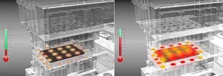
Surface Generation Ltd. (Oakham, UK) has developed technology that combines hardware and software to provide a ‘digital molding environment’ where precise thermal management enables massive reductions in energy consumption, cycle time and processing pressures. Termed PtFS, for Production to Functional Specification, this technology enables ‘pixelated’ temperature control up to 1,000°C and improved processing of even the most complex applications spanning thermosets and thermoplastics, all types of reinforcements including carbon fiber, and embedded electronics as well as metal and glass combinations in a variety of processes, including injection and compression molding.

The PtFS technology uses a fluid stream (typically air) flowing at variable rates through the mold, which is divided into multiple regions, like pixels, to heat and cool dynamically during cure using digital control. SOURCE: Surface Generation.
“We’re working with companies who are looking for step changes,” says CEO Ben Halford. “It might be in rate or reduced thickness or complexity. Basically, anyone who is dabbling with temperature and pressure.” Halford says PtFS has a very wide range of applications. “We’ve applied our technology to titanium, gorilla glass and polyurethane foam. And, of course, to composites. Mostly we work with manufacturers who are trying to break through established limits.”
Halford explains that PtFS dramatically improves temperature uniformity across the mold surface, which yields improved matrix viscosity control in the mold cavity. Enhanced viscosity control in compression and injection molding facilitates atypical process conditions such as reduced wall thickness (lighter components), elimination of weld lines/sink marks, aggressive adjacent section thickness changes and the use of high reinforcement volume fractions. Halford adds that PtFS does all of this while reducing press clamp, fill and closure pressures, because the input material temperature profile is no longer driven by the coldest, thinnest portion of the mold cavity. “Without digital control, you are essentially flying blind at processing. We offer far greater visibility.”
Injection Molding Case History — Increasing Fiber Content from 30% to 50%
Halford describes a recent injection molding project using a compound with 30% long-fiber reinforcement: “Just with good temperature control we can take that to 50%. But what we’re doing is not just limited to temperature control.” He says that the typical process comprises injecting a liquid material into the mold and applying a lot of holding pressure to counteract shrinkage from cooling. “We don’t do that. As soon as the tool is full we start solidifying back from the melt front to the injection gate, so you don’t have to worry about the shrinkage.” PtFS digital approach to mold tool control enables a pixelated view of the molding process that a traditional analog, isothermal approach doesn’t allow.
Halford asserts this process control enables Surface Generation to break through limits, for example in consumer electronics. Halford describes, “It is typical for manufacturers to use a 500-ton injection molding machine with accumulators, firing the liquid compound in like a cannon shot. But that fast rate is degrading the material, breaking down the long molecular chains. We can mold the same part with a 120-ton machine, mold it even thinner and with better properties.” He notes this also has economic benefits, “It costs $50/hr less to operate this smaller machine vs. the larger press.”
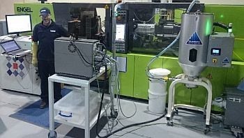
Using PtFS with an Engel injection moulding machine, Surface Generation reduced injection pressures by 75% and achieved strength and quality improvements in components trialed for large consumer electronics and automotive manufacturers. SOURCE: Surface Generation
Case History #2 — Solution to Warping in Laptop Cover
In another project, Surface Generation worked with a company producing a composite laptop cover, what is called an A-cover, which was very thin and flat with an embossed logo in the center. “The cover was a membrane strength design susceptible to deformation,” Halford explains. “Also, the fiber volume changed in the area of the logo. It was resin-rich around the logo, but fiber-rich inside the logo.”
Straight out of the press, the part stayed flat for a minute, says Halford, “but as it started to cool, it turned into a potato chip because of residual thermal stress.” He says what is needed is to cool the center first. “Say the press is at 200°C, you need to make sure everything arrives at 70°C at the same time but to do this you can only start cooling the outside when the center reaches 170°C – this way the whole part cools down to ambient without any stress.” He points out that the corners cool the fastest because they lose heat in two directions, while the edges cool next, losing heat in one direction and the “landlocked” center cools the slowest. “If you then throw any shape complexity into the mix,” warns Halford, “you could easily increase from three natural thermal zones to as many as 12, resulting in a much more complex thermal landscape.” He returns to the whole composite cover at 200°C: “Any isothermal approach cooled the corners first, the edges were still warm and the center was still hot. Part size is now locked while the middle is trying to shrink so when the center finally cools, you end up with residual stress.”
Using its proprietary software, Surface Generation programmed in business rules to drive PtFS pixelated temperature control and ensure that the center cooled at the same time as the edges and corners. “In fact, we treated the upper and lower tool surfaces differently, thanks to the digital control. Now, when you take the part out, everything is the same temperature and there is no residual stress in the part.” Yield increased from 75% to 95%, which is a pretty huge when the production volume is 200,000 parts/year.
Case History #3 — Thermoplastic Aerospace Components
Applying this pixelated approach to thermoplastic PEEK class aerospace primary, secondary and tertiary structures also yields considerable cycle time, energy consumption, capital equipment and quality benefits. Invar autoclave tools have been retrofitted to become free-standing, self-heated and self-cooled out-of-autoclave (OOA) cells capable of processing large-area, single-skinned or stiffened skin panels with cycle times of less than 2 hours at temperatures up to 450°C. The fact that the mold skin can be pre-heated can also be used to aid lay-up, bonding and, where required, achieve localized repairs. The same approach can also be applied for thermosetting systems with carbon epoxy or BMI mold faces. Matched PEI molds can similarly be outfitted with PtFS to produce net shape components from 1 to 25mm thick with pre-forming and consolidation cycle times of less than 1 hour.
Controlling Material Properties
Halford also notes that having localized control also allows crystalline or semi-crystalline thermoplastic polymers to be manipulated in ways that conventional isothermal approaches cannot. “We can cool at a very high rate, e.g. 1250°C/min, so that we can bypass a phase change,” Halford explains. He notes the material should be semi-crystalline, "but we can make specific areas amorphous so that the part is effectively flexible in some areas and stiffer in others. Think of a hinge.”
“It’s a combination of the hardware and software with pixelated control to manipulate geometry that you simply can’t achieve in any other way,” Halford summarizes. He notes there are also cases where parts have thickness that varies from 2 mm to 25 mm, producing wrinkles due to differential cooling. “You must manipulate those points with differing heat and cooling profiles to eliminate the issues.”
“We can also control the flexibility in polyurethane foam,” says Halford. “It is poured as a homogeneous mix. We will change the temperature and cooling rate locally to create a different reaction rate which gives a different cell size, resulting in different properties.”
Why would you want to do this? To incorporate dissimilar materials and/or electronics into a part using injection molding, compression molding or vacuum bagging. For example, a glass plate or an LED. “These can now survive the process,” says Halford. “So instead of having secondary operations, you can do it all in one shot. This provides incredible new design freedoms.”
|
|
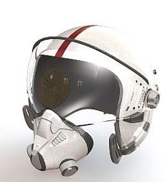
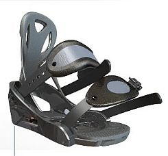
PtFS is used to made a wide variety of parts, including for applications like these.
SOURCE: Surface Generation.
Wide Range of Applications
Halford says Surface Generation is now having these discussions with industrial design teams in consumer applications. “We are working with very established OEMs but also new, disruptive companies who are not attached to any one process, but are quite willing to work from a clean sheet. For example, ‘What is the limit of a material with respect to thickness? How far can you push thin-ness?’ If you think about objects worn by consumers, this becomes very important.”
“We are having our busiest year in aerospace yet,” says Halford. “We’re seeing a lot of traction also in intelligent devices and systems integration, wearables, consumer electronics and integrated electronics.” He says Surface Generation is also working with large resin companies. “For example, say you have a 2-minute snap-cure system but want to get to cure times of 30 seconds or less. We can do that using our new Multiplexing process.”
Surface Generation will be presenting “Advanced Compression & Injection Molding of Complex Components from Neat & Reinforced Thermoplastics” at the upcoming Thermoplastic Composites Conference for Automotive (TCC 2016), co-located with the amerimold expo (June 15-16, Novi, MI, US).
Related Content
Plant tour: Albany Engineered Composites, Rochester, N.H., U.S.
Efficient, high-quality, well-controlled composites manufacturing at volume is the mantra for this 3D weaving specialist.
Read MoreManufacturing the MFFD thermoplastic composite fuselage
Demonstrator’s upper, lower shells and assembly prove materials and new processes for lighter, cheaper and more sustainable high-rate future aircraft.
Read MorePultrusion: The basics
A primer describing what pultrusion is, its advantages and disadvantages, and typical applications.
Read MorePEEK vs. PEKK vs. PAEK and continuous compression molding
Suppliers of thermoplastics and carbon fiber chime in regarding PEEK vs. PEKK, and now PAEK, as well as in-situ consolidation — the supply chain for thermoplastic tape composites continues to evolve.
Read MoreRead Next
“Structured air” TPS safeguards composite structures
Powered by an 85% air/15% pure polyimide aerogel, Blueshift’s novel material system protects structures during transient thermal events from -200°C to beyond 2400°C for rockets, battery boxes and more.
Read MoreDeveloping bonded composite repair for ships, offshore units
Bureau Veritas and industry partners issue guidelines and pave the way for certification via StrengthBond Offshore project.
Read MoreVIDEO: High-volume processing for fiberglass components
Cannon Ergos, a company specializing in high-ton presses and equipment for composites fabrication and plastics processing, displayed automotive and industrial components at CAMX 2024.
Read More


.jpg;maxWidth=300;quality=90)

