Portable wind turbine powers the warrior
DARPA-financed program puts wind energy to use for battery and system recharging.
Design Results:
- Composite wind turbine has a total weight, including support pole, of about 10 lb/4.5 kg, making it easily transportable by one person on foot.
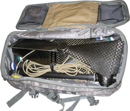
- Turbine components break down into easily assembled pieces that are short enough to fit inside an existing military backpack.
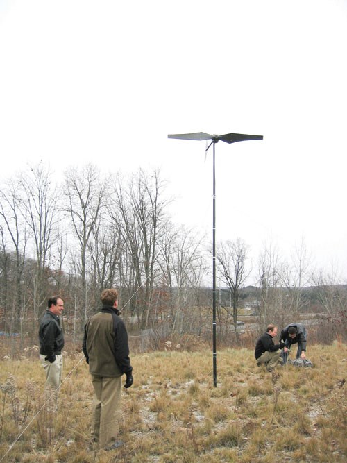
- The unit can be deployed by a single person, yet produces enough power to recharge batteries or run a critical small appliance.
Imagine yourself in a hostile battlefield as the sun sinks below the horizon. Your 80-lb/37-kg pack is loaded with gear and equipment, but you’re unable to radio your position because the radio’s batteries are dead and you’ve used all your replacements. That all-too-real problem now has a solution, thanks to the ingenuity of engineers at AdamWorks (Centennial, Colo.) and the initiative of Adamwork’s customer, the U.S. Defense Advanced Research Projects Agency (DARPA, Arlington, Va.).
AdamWorks, a growing design/build enterprise involved in multiple projects for aerospace and other clients, has developed a backpack-transportable wind turbine, under the DARPA-funded PoWER (Portable Wind Energy Recharger) initiative. The 10-lb/4.5-kg turbine can be erected in minutes by a single person and generates sufficient energy to recharge batteries or run a small appliance. Intended for the warfighter, the system also has far-reaching potential for recreational or remote-monitoring applications. “It might seem like a crazy idea, but this is an untapped market,” says AdamWorks’ president Kim Burquest. “Energy needs are a huge issue for the military and often a limiting factor for soldiers,” she notes. “The average warfighter consumes nearly 100 “AA” batteries on a five-day mission and they take up a significant portion of a soldier’s load.” The company designed and has built several of the turbines to satisfy its single-year DARPA contract, which ended in October 2010.
A tight design envelope
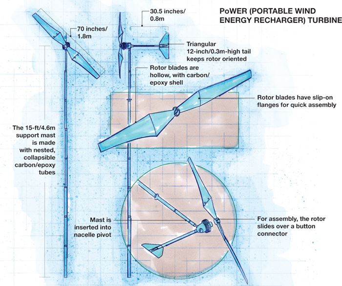
“We wanted to develop the lightest and the most practical recharger for field conditions,” declares AdamWorks’ Scott Noble, the lead engineer on the PoWER project. With that in mind, Noble’s team set tight design parameters for the turbine: It would be a two-bladed, upwind rotor with a diameter of 6 ft/1.85m, the size needed to generate sufficient electrical power for a recharger. Its maximum total weight, ~10 lb/4.5 kg (including blades, generator, pole and guy wires), wouldn’t overload a soldier. Further, no part would be more than 2 ft/0.62m in length, making the system compatible with existing pack dimensions. As it turned out, those constraints presented a considerable challenge.
First, the team’s aerodynamicist developed a blade with a straightforward shape and profile without twist, designed for optimal performance in a range of expected wind regimes. The initial design work was done in SolidWorks software from Dassault Systèmes SolidWorks Corp. (Concord, Mass.). Then, a finite element model (FEM) was developed with NX Nastran software from Siemens PLM Software (Plano, Texas). The FEM mesh was variously configured so that a number of different composite ply arrangements could be investigated, under several load cases. Noble notes that buckling stiffness was not a design driver because the blades experience very light out-of-plane loads. “Most of the load is caused by centripetal force,” he explains, “which acts outward as the rotor spins.” Based on this information, the load-case trials led the design team to a hollow blade design, with a thin, uncored, solid carbon/epoxy laminate shell, which yielded a blade design with the lowest possible weight.
Because the rotor design featured two blades, each approximately 2.75 ft/0.85m in length, each blade had to be jointed to permit disassembly into two sections that would fit within the system’s design 2 ft/0.62m “pack” length limit. The AdamWorks team designed the blade in two pieces, with a recessed flange joint, so that the outer section could be attached readily to the blade root section.
“It’s a simple slip-on flange right now, reinforced with metal screws to ensure integrity in the field,” says Noble. “We’re currently working on a snap connection to make it more user-friendly.”
The turbine design also includes a triangular tail to keep the rotor oriented properly into the wind. The tail features a simple solid laminate, approximately 12 inches/0.3m long. It connects to the back of the rotor hub via off-the-shelf, small-diameter roll-wrapped carbon/epoxy tubing. The hub itself is a composite shell designed to accommodate a small, cylindrical electric generator.
The team’s biggest challenge was achieving the target power output from a generator within the turbine’s weight budget. “We tried building our own generator, but couldn’t get enough power from it,” Noble recalls. “We ended up purchasing a small off-the-shelf wind turbine generator, but it was much too heavy. We then proceeded to tear it apart — we jettisoned everything we could to save weight yet still have it be functional.” The reconfigured generator weighs 4.5 lb/2 kg. It closely resembles a servo motor, employs permanent magnets to generate three-phase alternating electrical current and, he adds, is the heaviest part of the portable wind turbine.
Critical to the design, particularly given the necessity for segmented blades, was that the rotor be perfectly balanced, tip to tip, so that in operation, it would not be susceptible to vibration and instability as wind speed increases. To that end, Noble attempted to make the ply layups exactly the same and balanced the two (left- and right-hand) identical blades with the help of a gram scale. A small amount of lead was judiciously employed to ensure that both blades were the same weight.
A 15-ft/4.6m tall support mast completes the design. It comprises a series of nested, 2-ft/0.62m long, off-the-shelf, roll-wrapped carbon/epoxy tubes that lock together to form a rigid support tower. Thin guy wires attach to the top of the mast and stabilize it, via camping-tent-style titanium stakes, which are driven into the ground. The electrical wires from the turbine’s generator pass down through the support mast and can terminate in a standard plug or a customized plug that fits a particular application.
Using materials to best effect
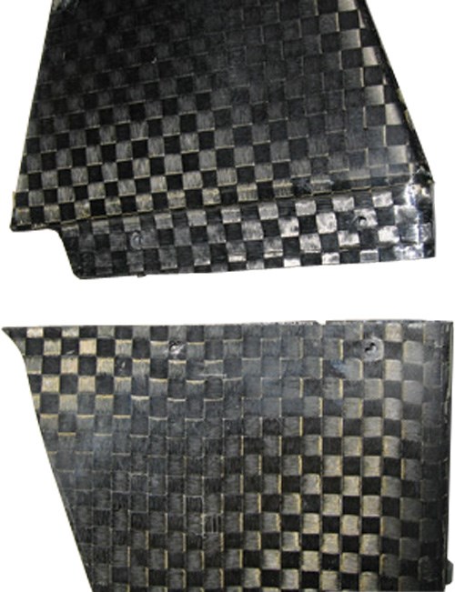
The AdamWorks team designed and built in-house two low-temperature open molds for the blades as well as molds for the tail and central generator housing, using composite tooling materials that it had on hand, supplied by PTM&W Industries Inc. (Santa Fe Springs, Calif.) and Advanced Composites Group Inc. (ACG, Tulsa, Okla.). The parts were hand layed, using four plies of a common aerospace 12K carbon/epoxy plain-weave prepreg, supplied by Toray Composites America Inc. (Tacoma, Wash.). After oven cure and minimal trimming and finishing, the blade shells were bonded together and the generator enclosed within the housing.
Initial trials proved that the turbine could be assembled and set up by a single person in less than five minutes. The team then mounted the assembly on a truck to test power output at specific wind speeds. According to Noble, winds must be at least 12 mph/19.3 kmh to produce power, which at a minimum is about 100 watts. At 35 mph/56.3 kmh, power output is approximately 800 watts. “Any higher than that, the voltage is too high and the unit gets pretty hot,” he reports. To slow the unit down in a wind gust or to stop it, the operator can simply pull on a string attached to the tail to pull the rotor out of the wind.
Concludes Noble, “The unit could be even lighter, with a few design tweaks and less material.” Both Burquest and Noble believe that the military will adopt the PoWER unit. “One possible scenario is that a military squadron will be equipped with our wind turbine as well as a solar energy panel, a fuel cell, and next-generation rechargeable batteries, to fulfill their energy needs in a standardized fashion,” adds Burquest, who relates that recreational applications, involving proprietary customers, are a possible next step. The quick-turnaround project proves the practicality of composites for critical renewable energy needs, wherever they’re found.
Editor's note: This article was approved by the U.S. Defense Advanced Research Projects Agency (DARPA) for “Public Release, Distribution Unlimited” on Feb. 9, 2011.
Related Content
Orbital Composites wins AFWERX award for Starfighter drone fleet
Under the TACFI contract, Orbital is implementing the AMCM process to build 3D printed composite multi-mission UAS aircraft, surpassing $10 million in government awards.
Read MorePlant tour: Renegade Materials Corp., Miamisburg, Ohio, U.S.
Renegade Materials is known for high-performance prepregs for aerospace applications. Following its acquisition by Teijin in 2019, the company has expanded capacity and R&D efforts on a range of aerospace-targeted materials.
Read More“Structured air” TPS safeguards composite structures
Powered by an 85% air/15% pure polyimide aerogel, Blueshift’s novel material system protects structures during transient thermal events from -200°C to beyond 2400°C for rockets, battery boxes and more.
Read MoreLarge-format 3D printing enables toolless, rapid production for AUVs
Dive Technologies started by 3D printing prototypes of its composite autonomous underwater vehicles, but AM became the solution for customizable, toolless production.
Read MoreRead Next
Core for composites: Winds of change
Core materials suppliers lean into the bracing breeze of big-blade challenges raised by the burgeoning wind energy industry.
Read MoreCarbon Fiber in the Wind
Is there a market for carbon composites in wind turbine blade construction? Yes, but the real question is, how big will it be?
Read MorePlant tour: Daher Shap’in TechCenter and composites production plant, Saint-Aignan-de-Grandlieu, France
Co-located R&D and production advance OOA thermosets, thermoplastics, welding, recycling and digital technologies for faster processing and certification of lighter, more sustainable composites.
Read More

