Share
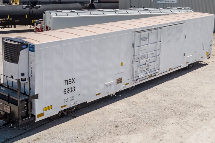
TrinityRail’s new refrigerated railcar features a composite primary load floor that enabled weight loss of 4,500 pounds and facilitated an innovative, industry-first secondary flooring system that allows transport of fresh produce or frozen foods in a single railcar. Photo Credit, all images: TrinityRail
There is, arguably, no mode of ground transportation less forgiving and more physically and mechanically challenging than rail freight. Railcars comprise, for the most part, an all-steel superstructure welded to an all-steel substructure that rides on an all-steel suspension on all-steel wheels rolling on an all-steel track. Every seam, bump and imperfection on the tracks is transferred directly from the track, through the wheels, into the substructure and, finally, to the superstructure and cargo.
Each car is also attached to another car on each end via all-steel couplers that transfer throughout the train via each car the mechanical energy generated whenever the train accelerates or decelerates. This causes couplers to pull and push on cars with longitudinal impacts that can exceed 1 million pounds, further straining each car’s structure.
Not to be forgotten is the commodity itself, which ranges from coal and lumber to frozen foods and fresh fruits and vegetables. These products exert a mechanical stress of their own on a railcar, which must be accounted for. Finally, on top of all of that, a railcar is expected to have a service life of at least 50 years, through heat, cold, humidity, rain, snow and wind.
The modern rail freight industry has coped with this harsh, high-impact, high-energy environment by emphasizing structural stiffness in its cars, favoring all-steel welded and bolted structures that are unyielding in the face of dynamic, cyclic, high-fatigue forces. And for many years, this stiffness-driven design model has worked well enough. That, however, is about to change. A Texas-based railcar manufacturer is on the cusp of introducing a refrigerated boxcar that will feature, for the first time in the rail freight industry, a composite primary load floor that not only saves weight, but increases payload volume.
Rethinking the reefer
TrinityRail (Dallas, Texas, U.S.) manufactures a full range of railcars for the tank and freight shipping industry. These include tank cars, covered hoppers, auto carriers, flat and intermodal cars, gondolas, open hoppers and boxcars. And within the boxcar category, there are three varieties — standard boxcars for transport of dry commodities, insulated box and refrigerated (“reefer”) cars for transport of fresh produce or frozen food.
Reefer cars are equipped with HVAC systems and come in two versions, one designed to transport fresh produce and the other to transport frozen food. Despite the fact that each reefer offers a temperature-controlled environment, their floors are different, and are designed specifically for shipping either fresh or frozen product. Because of this, rail operators face, daily, a logistical challenge in retaining access to an adequate number of each type of reefer to avoid spoilage.
There is also a second problem common to current reefer boxcars: their all-steel construction is highly segmented and therefore prone to develop thermal breaks that erode the ability of the cars to maintain temperature setpoints. TrinityRail reports that 40% of thermodynamic leakage in current boxcars is from air escaping through thermal breaks.
Third, says Carter Andrews, a mechanical engineer at TrinityRail, is the challenge of thermal expansion. Temperature in a reefer car transporting frozen food is typically set to -10°F. On hot days, the temperature on the railbed can be 120-140°F. “That temperature differential from outside to inside wreaks havoc on cars,” Andrews says. “The cars are literally fatiguing themselves apart. The floors see a lot of cracking and break-up of the insulation, which causes more thermal shorts. We wanted a car that was not prestressed and not loaded all the time.”
Finally, there is forklift problem. Current reefer cars used to transport produce feature floors of bare corrugated aluminum. This corrugation allows airflow around the cargo, but it also is destructive to forklift tires as they turn atop the floor. As a result, tires are destroyed quickly and rubber fragments accumulate in the corrugations. “We went to our customers and watched these guys loading produce,” says Ken Huck, director of product development at TrinityRail. “We asked what they liked and what they didn’t like. That’s what gave us the ideas and the concepts to solve these issues.”
In 2017, TrinityRail began an effort to rethink its reefer boxcars, led by Huck and Andrews. “We looked at all of these issues and said, ‘How can we make one thing that solves all these problems?’” says Andrews, adding that he was also eager to evolve railcar design that has changed little in 20 years. “We had an opportunity to really improve the design, but we had to do some very specific things. One of them was lightweighting the car. Cars were growing too much in weight. As you start adding complexity, they start growing exponentially in weight. I had very specific ideas about the floor and how to improve airflow.”
Meanwhile, Composite Applications Group (CAG, McDonald, Tenn., U.S.) was just coming off a success, having helped connect long-haul trailer manufacturer Wabash National (Lafayette, Ind., U.S.) with Structural Composites (Melbourne, Fla., U.S.) for the development of what would become the over-road freight industry’s first use of structural composites in the walls and floor of a refrigerated trailer.
The result, developed with Structural Composites, was Wabash’s Molded Structural Composite (MSC) Cold Chain technology, deployed in the floor and walls of its reefer trailer. The heart of the MSC Cold Chain product is Structural Composites’ Prisma technology, which comprises a series of foam-cored glass fiber panels 4-36 inches wide and 0.75-4.0 inches thick. Length of the panels can be adjusted to the height and width of trailer walls. Several of these panels are subsequently co-molded in a compression process to build the final MSC structures, which form the walls and floors of a Cold Chain trailer.
For the floor of the Cold Chain trailer, instead of a typical steel cross-member structure with an insulated floor attached to it, a comolded and CoCure-bonded assembly of hollow aluminum extrusions (that allow cold air to flow through the floor) and Prisma beams are laminated directly on the metal. Structural Composites’ patented CoCure strain-tunable coating, resin and adhesive, a mixture of commodity polyester with varying percentages of polyurethane, bonds the beams to the metal — the hybrid metal/composite structure is laminated and cured as a single 53-foot-long part.
Jeff McCay, CEO of CAG, says his firm had facilitated the Wabash/Structural Composites relationship and helped develop the suppliers and supply chain Wabash needed to bring the innovative reefer trailer to market. McCay, subsequently, was invited to talk about CAG’s experience with Wabash at a marine-focused event hosted by Trinity Industries, parent of TrinityRail. Huck attended the same event, saw McCay’s presentation there and realized the potential for composites use in the floor of a new TrinityRail reefer car. It was, in short, the technology he and Andrews needed to bring their ideas to life. “We saw what Jeff McCay had done and said, ‘This is a good opportunity to fix some of the problems we have and improve the performance at the same time,’” Huck says. “We had strict cost and strength requirements, so if we could meet those and solve these problems, it would be a win-win.” This insight, combined with Andrews’ ideas for reducing railcar weight, set the pair down the path toward a new design. “Ken and I, coming together and combining our ideas, allowed us to make the car,” says Andrews.
CAG, for its part, says McCay, was looking for opportunities to leverage its composites development experience with Wabash in other non-trucking markets — opportunities to take composites design and engineering lessons learned in one end market and apply them in another. Huck approached McCay at that Trinity Industries event, launching what would become a collaborative effort to bring this new reefer car design to life.
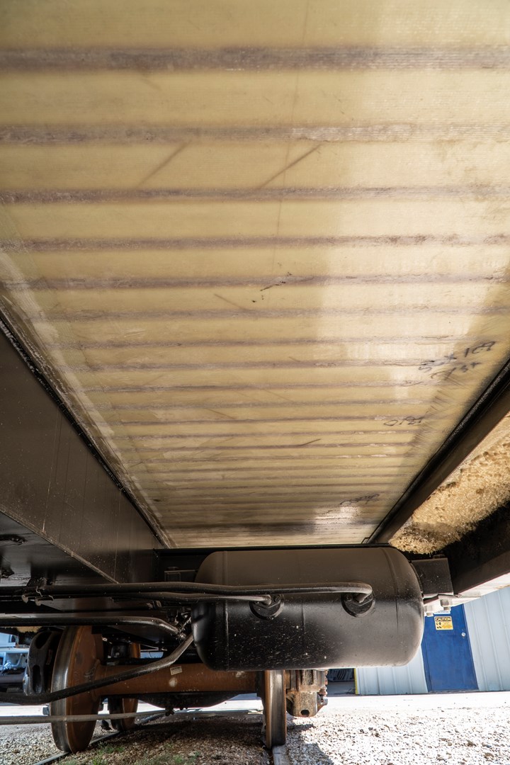
This view from below the railcar shows the underside of the composite primary load floor. The Prisma beams are clearly visible, spanning from the side of the car to the center sill, the black structure on the left in the photo. The beams are 109 inches long and span the full width of the railcar. The composite load floor helps mitigate CTE mismatch between the temperature in the car and the temperature outside. It also provides critical vibration-damping capabilities.
Boxcar 101
Applying composites to a reefer railcar is not trivial, and requires understanding of the thermal, mechanical and regulatory forces at work. First, the thermal: A reefer transporting fresh produce must maintain a temperature of 34-38°F, with good air circulation to vent produce off-gases, slow the produce ripening process, maintain freshness and minimize spoilage. A reefer railcar transporting frozen food requires a flat, cold plate floor and a constant temperature of -10°F.
Second, the mechanical: Almost all railcars, regardless of type, are loaded via forklift, which puts uncommon pressure on the floor of the car. Railcar floors are rated for a forklift load of 25,000 pounds/axle and must also endure the wear and tear of forklift wheels driving over and rotating on them for 50 years.
Third, the regulatory: In the U.S., the gross weight limit of any railcar, whether boxcar, tanker or flatcar, is 286,000 pounds (130,000 kilograms), with about 102,000 pounds (46,266 kilograms) of that taken up by the car itself, in the boxcar category. A boxcar also has a limited interior volume, dictated in part by its exterior dimensions, which are set by Association of American Railroads (AAR) regulations to ensure the car can pass under bridges, through tunnels and past other close-by structures. The AAR boxcar exterior height limit is 17 feet (5.2 meters) from top of rail to top of car. The exterior width limit is 10 feet, 8 inches (3.3 meters). Car length varies, but is usually offered in lengths of 50, 64 or 72 feet (15.2, 19.5, 23 meters). Reefers are typically 64 feet or longer.
Logic dictates that the weight limit of a reefer is reached more quickly with a dense commodity, like frozen food, while the volume limit, usually about 7,800 cubic feet (221 cubic meters), is reached more quickly with a less dense commodity, like broccoli. Given these limits, it doesn’t take an engineer to readily understand that a boxcar design that reduces mass and increases volume could be highly advantageous to a rail operator.
The solution: A composite primary load floor
Given these parameters, and given the success of Wabash’s Cold Chain product, Huck and Andrews seized on the floor as the best place to apply composites in the TrinityRail design. They also seized on the opportunity to develop a load floor that would allow the rail operator to quickly and easily convert a reefer from insulated to refrigerated, and vice versa. Doing so would create a new category of hybrid reefer — one that can accommodate two classes of temperature-sensitive commodities.
“Cars today are designed for one or the other, fresh or frozen,” says Huck. “They rarely use them outside of what they were designed for, and when they do, they have a lot of compromises they give up. We were able to come up with a design in which one car can convert very quickly and easily between fresh and frozen commodities.”
This was not so easily done. The TrinityRail value proposition for a composite reefer floor revolved around these requirements: It must interface with and attach to a boxcar’s steel substructure, absorb CTE differences between the steel substructure and other structures, support 180,000-185,000 pounds (81,646-83,914 kilograms) of commodity, support the dynamic mass and stress of a 25,000-pound forklift loading the commodity, absorb the cyclic longitudinal and latitudinal loads from rail and car impacts up to 1.2 million pounds, provide a thermal seal to minimize temperature variability, reduce weight against the steel incumbent, meet current strength targets, be long-term cost-efficient and be easily assembled, installed and maintained. And it must do all of this without fail over a period of 50 years.
Working with CAG and partners Wabash and Structural Composites, Andrews and Huck began to design a new boxcar load floor that can be thought of as two separate but cooperative structures. The first is the composite primary load floor, anchored to the car’s steel substructure and steel walls. The second structure, the secondary load floor, is comprised of a series of aluminum extrusions that are attached to the top of the composite primary load floor.
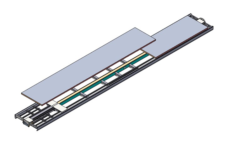
This rendering shows how the composite primary load floor is segmented in TrinityRail’s new refrigerated car. The entire floor is 72 feet long, but separated into two structures, one 50 feet long and the other 22 feet long. This allows TrinityRail to ship the floor structure in standard trailers and provides an expansion joint as the floor sees temperature change.
First, the composite floor. As noted, the composite floor design is derived primarily from the one developed for the Wabash Cold Train reefer trailer floor. It is fabricated in two sections; one is 50 feet (15.2 meters) long and the other is 22 feet (6.7 meters) long, for a total floor length of 72 feet (22 meters). This was done to make the floor easily transportable via flatbed truck, and to create a thermal expansion joint in the floor. Floor architecture consists of a series of Prisma beams, side by side and as long as the boxcar is wide. Each Prisma beam is 4.75 inches (121 millimeters) tall, 4.25 inches (108 millimeters) wide and 109 inches (2.8 meters) long. They are comprised of 2-pounds/cubic foot polyurethane foam core wrapped with a glass fiber non-crimp fabric (NCF).
The CoCure hybrid metal composite floor is made by first laying what will be the top surface of the floor — an aluminum sheet — on a stable form, top side down. After preparation, a proprietary CoCure adhesive blend is applied to the aluminum sheet. Fibers, resin and Prisma preforms are saturated, placed on the sheet and then compression molded to the final dimensions. To unitize the floor structure, the Prisma beams are assemble side by side traversely across an aluminum sheet. Where needed, the beams are wrapped with additional glass fiber. Selective use of carbon fiber provides the needed molded dimensional stability from the asymmetric metal hybrid laminate. In a portion of the floor near the joint between the 50- and 22-foot sections, 3 x 1-inch thick x 24-inch-long steel bars are embedded within the Prisma beams for later connection to the railcar underframe. The fully assembled and complete composite primary floor, says Huck, is 5 inches (127 millimeters) thick.
As noted, the composite floor actually consists of two sections, which abut each other and meet over one of the underframe cross-bearers. This is a stark contrast to legacy designs, says Andrews: “This is more of a homogenous floor. A lot of other floors are made up of a lot of joints, and wherever you have a lot of joints, you have a lot of thermal shorts. So in previous cars, they would split a 72-foot floor up into anywhere from eight to 12 to 16 joints. And our floor has one joint.”
Atop the composite primary floor is the secondary floor where further innovations have enabled TrinityRail to integrate fresh and frozen reefer features in a single car. The first layer of the secondary floor is the above-referenced aluminum plate bonded to the Prisma beams. Atop this aluminum plate is a layer of corrugated aluminum, and over this is a series of 16 aluminum tread plates, each attached with four hand-actuated, quarter-turn fasteners (64 total). Each plate can be quickly and independently rotated to change the car from fresh produce to frozen, thanks to venting in the diamond plate that, depending on its orientation relative to the corrugation, either allows or prevents return air flow through the tread plate, around the commodity and out of the car as needed.
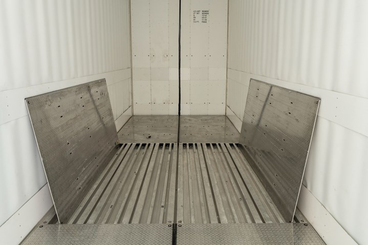
Atop the composite primary load floor is the secondary load floor. It consists of a corrugated aluminum floor, seen here, topped by 16 diamond-plate aluminum panels. When a shipper wants to configure the floor to ship fresh produce, the panels can be rotated to allow slots in the panels to align with gaps in the corrugation. This allows return air to circulate through and up through the slots to vent produce off-gasses. When a shipper wants to configure the floor to ship frozen food, the panels can be adjusted again to seal off the airflow and provide a solid, cold surface.
There are multiple benefits to this floor design, say Huck and Andrews. First, because each plate can be rotated independently, rail operators can customize air return patterns throughout the car, depending on where the commodity is located. Second, the aluminum plate can be easily and quickly cleaned to meet U.S. Food and Drug Administration (FDA) requirements for handling of produce. Third, the 16-plate/64-fastener design makes railcar assembly much simpler and more flexible. The legacy design deployed 1,700 rivets in the floor, which, by design, made it impervious to alteration — hence the insulated-only/reefer-only boxcar limitation that currently predominates.
There are other advantages conveyed by the composite floor as well. Huck notes that it helps attenuate CTE issues that often exist in railcars: “The secondary floor is all aluminum and the frame is steel, and they have very different values for coefficient of thermal expansion. So the composite primary floor is in between the steel and the aluminum top plate, and that helps us absorb those deflections from thermal expansion.”
Ultimately, the composite floor rests on and is bonded to a steel substructure that consists of a center sill that runs the length of the car, and four equidistant steel cross-bearers attached and perpendicular to the center sill. Andrews says the adhesive used to bond the floor, supplied by 3M (St. Paul, Minn., U.S.), has an elongation greater than the CTE of the floor, “so the floor can expand and contract without cracking the glue.” In addition, there are shear connectors — one pair for each of the two floor sections — in the form of 0.5-inch brackets welded to the center sill that can support all of the floor impact loads by themselves. “Since this is our first go-round with composites, we wanted to have a backup shear connector just in case something came unbonded,” Andrews says. The sides of the primary floor are bonded to the railcar side sills with the same 3M adhesive.
Although the composite floor is lighter than the legacy floor it replaces, it’s in the substructure that the composite floor produces most of the weight savings TrinityRail sought. The legacy substructure consisted of a center sill and four cross-bearers, like the new design, but also had 14 steel cross-ties and 16 longitudinal stringers. All 14 cross-ties and 14 of the longitudinal stringers were eliminated in the new floor design because of the strength of the composite floor, allowing TrinityRail to take 4,500 pounds (2,042 kilograms) out of the reefer. These savings, in the weight-sensitive rail freight world, is profit in the form of expanded payload capacity. “Some of these cars, depending on the commodity, might weigh out before they cube out, and some cube out before they weigh out,” Huck says. “But we have increased the weight capacity as well as the interior volume on this car.”
More pointedly, says Andrews, “Two tons is equal to two pallets of French fries.” The reduced substructure also reduced the number of contact points with the floor, which helps minimize thermal transfer among all structures. In addition, says Andrews, “Although we took 4,500 pounds of steel out of the underframe, the FEA still shows that we have a stiffer car than the original. Not by much, but it’s better.”
There is an additional significant benefit, say Huck and Andrews, that the entire floor structure has enabled in the railcar design. This benefit harkens back to the original stiffness-driven ethos that has been the mindset of railcar design for the last 100 years. “Railcars are the kings of vibration,” says Andrews, adding that traditional railcar design includes significant focus on applying more steel to make sure the natural harmonic node of the car remains “above the threshold where the car is going to tear itself apart. In the new car, the composites could have a massive [positive] effect on the vibration. We’re talking about the car lasting longer and seeing less fatigue because the vibration will be dampened. This will benefit the commodity as well, providing a gentler ride.”
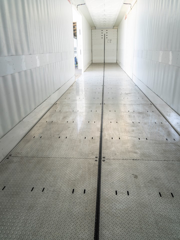
Full length and width of TrinityRail’s new reefer, with secondary floor installed. The hybrid function of the car will allow shippers to quickly and easily adjust to accommodate fresh produce or frozen food. The new floor is also thinner and provides an additional 150 square feet of storage volume.
Direct/indirect benefits, next steps
The ultimate benefits conveyed by the composite railcar floor vary from the direct to the indirect. Directly, as noted, the floor enables a hybrid fresh/frozen reefer design, reduces car weight by 4,500 pounds and expands payload capacity. In addition, the total floor height of 8 inches (203 millimeters) is 3 inches (76 millimeters) less than the previous design, which expands the storage volume of the car by 150 cubic feet (4.2 cubic meters) and increases height clearance at the door for forklifts. It also enables a minimum 5% improvement in thermal performance compared to the legacy design. From a manufacturing perspective, the composite floor allowed TrinityRail to reduce piece/part count from more than 2,000 in the legacy floor to approximately 150 in the new floor. In addition, the new floor, because it’s lighter weight, requires less labor time to install.
Indirectly, the weight savings offers the potential to reduce the number of railcars needed to haul a given set of cargo, increase transport efficiency and, thanks to the improved thermal efficiency, reduce the energy required to cool the reefer. In addition, the hybrid functionality of the car simplifies maintenance and spare parts management and obviates the logistical challenge rail operators face to keep track of which reefers are made to transport fresh produce and which are made to transport frozen food.
Huck and Andrews say the experience of developing the composite floor has opened their eyes to expanded use of composites in other railcar applications. Andrews notes that the unit cost of the composite floor is less than the legacy floor, and the labor and weight savings and other benefits amplify its advantages. In addition, there is a sustainability and efficiency benefit that is impossible to ignore. Ultimately, says Huck, the boxcar floor project checked all of TrinityRail’s boxes.
“CAG helped us pull together a variety of composites industry suppliers, many of whom aren’t used to working in the rail industry,” he says. “The project exceeded our expectations. Our cost, our strength, our weight, our performance needs were all met or exceeded.”
The TrinityRail composite floors are fabricated on a contract basis by Wabash National at its facility in Little Falls, Minn., U.S., and shipped to multiple railcar assembly facilities that TrinityRail operates in North America. That supply relationship likely will continue indefinitely. CAMX 2021, Oct. 19-21 in Dallas, Texas, U.S., will mark the public debut of the TrinityRail composite floor, to be followed by market introduction in late 2021/early 2022.
In the meantime, Huck and Andrews say they are working with CAG and Structural Composites on a second project to develop another composite structure. What that structure is and where it’s located in the railcar remains to be seen. Regardless, TrinityRail sees composite materials in its future, and likes the potential.
“Based on the success of this project, we look forward to working with CAG on other projects,” says Huck. “With what we’ve already shown and what we will show in the future, it’s clear that composites can play a role in the rail industry. Trinity can meet sustainability goals, cost and weight targets and we can get better performance. Our customers, the shippers, will benefit, but so will the railcar owners, the railroads and, ultimately, the consumer. If we have less waste of product through better temperature control, many people will benefit.”
Related Content
The next evolution in AFP
Automated fiber placement develops into more compact, flexible, modular and digitized systems with multi-material and process capabilities.
Read MoreCombining multifunctional thermoplastic composites, additive manufacturing for next-gen airframe structures
The DOMMINIO project combines AFP with 3D printed gyroid cores, embedded SHM sensors and smart materials for induction-driven disassembly of parts at end of life.
Read MoreJeep all-composite roof receivers achieve steel performance at low mass
Ultrashort carbon fiber/PPA replaces steel on rooftop brackets to hold Jeep soft tops, hardtops.
Read MorePlant tour: Spirit AeroSystems, Belfast, Northern Ireland, U.K.
Purpose-built facility employs resin transfer infusion (RTI) and assembly technology to manufacture today’s composite A220 wings, and prepares for future new programs and production ramp-ups.
Read MoreRead Next
Plant tour: Daher Shap’in TechCenter and composites production plant, Saint-Aignan-de-Grandlieu, France
Co-located R&D and production advance OOA thermosets, thermoplastics, welding, recycling and digital technologies for faster processing and certification of lighter, more sustainable composites.
Read MoreAll-recycled, needle-punched nonwoven CFRP slashes carbon footprint of Formula 2 seat
Dallara and Tenowo collaborate to produce a race-ready Formula 2 seat using recycled carbon fiber, reducing CO2 emissions by 97.5% compared to virgin materials.
Read More“Structured air” TPS safeguards composite structures
Powered by an 85% air/15% pure polyimide aerogel, Blueshift’s novel material system protects structures during transient thermal events from -200°C to beyond 2400°C for rockets, battery boxes and more.
Read More


