Resin transfer molding and preforms for jet engine stators
New 3-D woven preforms and nanofillers will improve part quality and reduce manufacturing costs.
Jet engines first appeared on aircraft during World War II. By 1945, the advantages of the jet had become clear, and today jets dominate the aviation industry. Despite the complexity of the modern jet engine, the principle behind its operation is quite simple: air is drawn into the engine, accelerated and then expelled, increasing its momentum in the process. A force develops to counteract the change in momentum, which is the engine's thrust.
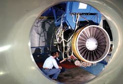
Different types of jet engines have been developed for a variety of operating conditions. The turbofan, invented by Rolls-Royce (Chantilly, Va., U.S.A.), runs best in the 400 to 1,050 kmh (250 to 650 mph) range, and thus is the most common type of jet engine in use today. The Rolls-Royce AE3007 is one example of a turbofan engine. It provides 2,700 kg to 4,100 kg (6,000 lb to 9,000 lb) of thrust. It is used on a variety of aircraft, including Embraer regional aircraft, Cessna Citation business jets and even the Global Hawk unmanned surveillance aircraft. Overall, this engine family powers more than 40 percent of the regional airline market.
Engine components
All jet engines comprise four basic components. Air enters the engine through the compressor, where its pressure and temperature are increased. Next, the air moves into the combustion chamber (or chambers) where fuel is injected and burned, both heating and expanding the air. As the air expands, it moves through the turbines, which turn the compressor. Finally, the air accelerates through the exhaust nozzle, producing the high velocity air jet and hence the engine thrust.
In a turbofan engine, the turbines also drive a large fan located in front of the compressor. The fan increases the airflow into the engine, thereby increasing thrust and improving fuel economy. Some of the air is diverted around the core of the engine, bypassing the compressor, combustion chambers and turbines. This bypass air remains relatively cool, and mixes with the hot core air in the exhaust nozzle. The lower exhaust temperature has the benefit of reducing noise, making turbofans much quieter than other types of jets. The ratio of the bypass air mass to the combustor air mass is called the bypass ratio. Engines with low bypass ratios draw in less air and accelerate it to high speeds; engines with high bypass ratios draw in more air and accelerate it to comparatively lower speeds. The low bypass engines provide better high-speed and high-altitude performance; the high bypass engines provide better low-altitude and subsonic performance. High bypass engines like the AE3007, which derive up to 85 percent of their thrust from the fan, are quieter and more efficient than low bypass engines, but also larger and more complex.
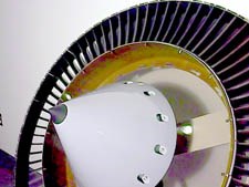
The inlet fan, as well as each stage of the compressor, comprises two stages: a rotating set of blades followed by a stationary set of blades called a stator. The stator helps direct the turbulent flow coming off of the rotating blades. At the same time, it slows the flow, increasing the static pressure and temperature, which is especially important in the compressor.
Composite bypass vanes
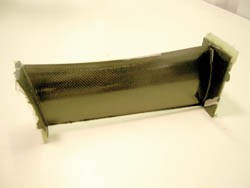
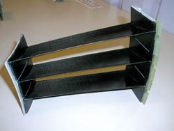
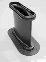
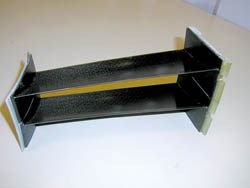
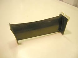
The AE3007 fan stator has 74 Fan Outlet Guide Vanes (FOGVs), located directly behind the inlet fan. Texas Composite (Boerne, Texas, U.S.A.) makes the composite vanes using an RTM process. The blades are made individually and then bonded into triplet (three-vane) and doublet (two-vane) assemblies: a 74-vane stator comprises 24 triplets and one doublet. According to Shawn Speer, sales engineer for Texas Composite, production peaked at 400 assemblies (doublets and triplets) per week, or 50,000 vanes per year, in 2000. By the end of 2003, a total of 65,000 assemblies had been shipped.
Each vane is about 152 mm/6 inches long, and 38 mm to 51 mm (1.5 inches to 2.0 inches) wide. The blades were designed by Rolls-Royce and incorporate a number of materials, including T300 and M40J carbon fibers (Toray Carbon Fibers America, Trophy Club, Texas, U.S.A.); fiberglass and Kevlar from a variety of third-party suppliers that are on Rolls-Royce's approved vendor list; and Inconel, a nickel alloy commonly used in high-temperature aerospace applications, for the leading edge. Compared to a traditional metal vane, the composite design yields a part that is significantly lighter and stiffer -- attributes that are important for the highly dynamic environment in which they operate. Texas Composite assisted with early design, providing input for manufacturability. "Developing a net-shape molding process for the bypass vanes proved a challenge due to the thinness of the airfoil section and the extremely small leading and trailing edge radii," says Mark Folsom, a Texas Composite engineer. "The RTM process itself required considerable work to develop a system that resulted in predictable resin flow with minimal void volumes within the part on a production basis."
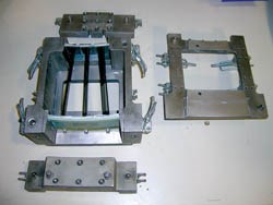
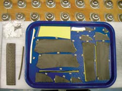
Thomas Unruh, project engineer at Texas Composite for the AE3007 vanes, describes the current layup process. The composite materials are cut into complex shapes on a Gerber Technology Inc. (Tolland, Conn., U.S.A.) computer-controlled cutting table and then assembled into kits. Each kit contains the 26 individual pieces, including a woven 3-D preform and the Inconel leading edge, required to make a single vane. The preform is woven by T.E.A.M. Inc. (Slatersville, R.I., U.S.A.) and forms the core of the vane. The pieces are laid out in a "shadow box" tray for easier handling and product accountability. Technicians use a binder to assemble the 2-D plies and the 3-D preform into the final dry RTM preform assembly, which is then placed in a coffin-style tool and delivered to the RTM molding area.
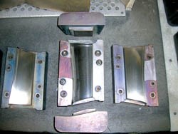
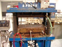
In the molding area, a Tactix 123 epoxy resin from Huntsman Advanced Materials (Houston, Texas, U.S.A., formerly Ciba Specialty Chemicals of Tarrytown, N.Y., U.S.A.) is injected and cured at 177°C/350°F in a three-hour cycle. Four vane tools are processed simultaneously in a single RTM mold. The RTM process yields a smooth, aerodynamic vane surface right out of the mold, but the end platforms used for handling and mounting require deflashing. The individual vanes are first taken to an inspection table to make sure none of the preform parts moved during the molding process. If any have, the part is rejected and sent to the Material Review Board for later disposition. After inspection, the vanes are run through a Haas Automation Inc. (Oxnard, Calif., U.S.A.) CNC machine that has been programmed to automatically deflash the parts and to machine a tight tolerance radius into the edges. A final hand deflashing provides the necessary detail that is too fine for the machine and prevents chipping of the material. The entire deflashing process takes about an hour.
Next, the vanes are placed in bonding jigs to form doublets or triplets. The jig also serves as a "go/no-go" gauge: if the vanes don't fit within the jig tolerance, then something went wrong in the molding or machining processes and they must be rejected. The vanes are then bonded together with an inner and outer strap using a 3M (St. Paul, Minn., U.S.A.) adhesive and cured in a bonding oven at 66°C/150°F.
After bonding, any excess adhesive is removed in another deflashing process. Slots are then ground into the platforms for assembly of the vanes into the fan case, one of the structures that holds the vanes in the engine. Finally, the vane assemblies are cleaned, sealed and taken to Quality Assurance (QA), where they are double-checked and then sent to shipping.
"It is a fairly complex process because of the extensive amount of human interaction," explains Unruh. "We are always working to improve the process and ultimately decrease the overall cycle time." Introduction of the shadow box trays helped to organize the parts, making them easier to locate and account for during layup. The Haas CNC machine, brought in a few years ago, expedited the deflashing process, originally done entirely by hand. Additional bonding fixtures enable technicians to begin an assembly while another is curing in the bond oven.
3-D preforms simplify manufacturing
While these changes incrementally reduced manufacturing costs and processing time, cut material usage and helped make the overall system more robust, substantial gains in processing efficiency thus far have been limited by the complexity of the parts. However, Texas Composite and Rolls-Royce are investigating thermoplastic resins and other design changes to further reduce processing times and other costs.
Based on its experience with the preform at the core of the AE3007 vanes, Texas Composite is developing for a new engine program a stator vane made primarily from a single 3-D preform. The new vane is about twice the size of the AE3007 vanes in all dimensions -- length, chord and thickness. The large size means the aerodynamic forces on the vane are much higher, resulting in larger deflection forces, which increases the delamination stresses.
Therefore, the new design comprises a 3-D core preform that features through-thickness Z-fibers to help prevent delaminations and, in general, produce a more robust part. The preform is overwrapped with one ply of woven material to provide a smooth, aerodynamic surface, and the part incorporates a metal leading edge. The RTM kit is thus much simpler than the current 26-piece kit, resulting in a much simpler layup process. After preparation and trimming, the preform is overwrapped, placed in the RTM mold and shot either with a low-temperature, one-part epoxy resin or a high-temperature bismaleimide (BMI). Different resins and metals are used because the vanes are used at two different locations in the engine, one at high temperature and the other at low temperature. The metal leading edge pieces are acid-etched, bond-primed and applied as a secondary operation after molding. Texas Composites is looking at alternative nondestructive test (NDT) methods that can be used on these and similar parts that have varying geometries and thicknesses. Ultrasonic C-scan and radiographic X-ray methods have been used with mixed results.
Unlike the AE3007 vanes, however, the new vanes will not be post-bonded into doublets and triplets. Instead, the high-temperature vanes will be manufactured and delivered as single-vane units, and the low-temperature vanes will be molded as pairs.
Texas Composite has worked closely with T.E.A.M. to develop the new preform. When the Z-fibers are woven through the preforms, interesting things happen on a micromechanical scale. "Imagine driving a spike through a 2-D woven ply," explains Folsom. "The spike separates the fibers, creating a small triangular opening." During molding, these pockets fill with resin, changing the localized fiber density, coefficient of thermal expansion (CTE) and shrinkage of the neat resin and resin-saturated fibers. The two companies are currently looking for ways to solve these problems. One general approach is to modify preform parameters, including the density and depth of the Z-direction weaving, and the tow size of both in-plane and through-thickness fibers. Texas Composite also hopes to be selected for a Small Business Technology Transfer (STTR) award, similar to the Small Business Innovation Research (SBIR) awards. The company proposes to use a variety of nanofibers and nanofillers to bring the properties of the resin-rich areas closer to the properties of the overall composite.
While the two companies have some preliminary test results of different weave parameters, the STTR award will not be announced until August 2004. The schedule is tight, though: the new vanes go into qualification this fall, and production is scheduled for the middle of 2005 for an as yet undisclosed aircraft customer. Structural testing has already been performed on flat panels made with the same 3-D architecture as the preforms. The next stage of the qualification process will be aerodynamic performance and durability testing at the customer's site.
The designs for both the AE3007 vanes and the new 3-D vanes reflect Texas Composite's philosophy of delivering a "complete composite solution." As Folsom describes it, "Everything we produce is based on composites. We perform a substantial amount of assembly and finishing operations so that our customers can simply install the parts without further processing." With the development of the 3-D vanes, Texas Composite is further streamlining the manufacturing, removing as much touch and assembly labor from the process as possible.
Related Content
Manufacturing the MFFD thermoplastic composite fuselage
Demonstrator’s upper, lower shells and assembly prove materials and new processes for lighter, cheaper and more sustainable high-rate future aircraft.
Read MoreSulapac introduces Sulapac Flow 1.7 to replace PLA, ABS and PP in FDM, FGF
Available as filament and granules for extrusion, new wood composite matches properties yet is compostable, eliminates microplastics and reduces carbon footprint.
Read MoreJeep all-composite roof receivers achieve steel performance at low mass
Ultrashort carbon fiber/PPA replaces steel on rooftop brackets to hold Jeep soft tops, hardtops.
Read MorePlant tour: Spirit AeroSystems, Belfast, Northern Ireland, U.K.
Purpose-built facility employs resin transfer infusion (RTI) and assembly technology to manufacture today’s composite A220 wings, and prepares for future new programs and production ramp-ups.
Read MoreRead Next
Plant tour: Daher Shap’in TechCenter and composites production plant, Saint-Aignan-de-Grandlieu, France
Co-located R&D and production advance OOA thermosets, thermoplastics, welding, recycling and digital technologies for faster processing and certification of lighter, more sustainable composites.
Read MoreVIDEO: High-volume processing for fiberglass components
Cannon Ergos, a company specializing in high-ton presses and equipment for composites fabrication and plastics processing, displayed automotive and industrial components at CAMX 2024.
Read More“Structured air” TPS safeguards composite structures
Powered by an 85% air/15% pure polyimide aerogel, Blueshift’s novel material system protects structures during transient thermal events from -200°C to beyond 2400°C for rockets, battery boxes and more.
Read More


