Sea and land transport: Hydro elevation
Composites lightweight and toughen the hull and superstructure of this transplanted amphibious naval hovercraft.
Well-equipped navies in the U.S. and elsewhere in the developed world make extensive use of hovercraft for sea-to-land transport. Designed to “float” on a cushion of air, hovercraft are made to traverse both water and land surfaces, emulating a sort of low-altitude aircraft. Of all the possible applications for composites, few are better suited than a hovercraft to take advantage of the strength-to-weight benefits they promise. Given the high penetration of composites elsewhere in the boatbuilding industry, it’s somewhat surprising to discover how little this material has been applied to these amphibious watercraft.
Historically, hovercraft are of aluminum construction. Only in the past 17 years have composites earned their way onto this vessel type with one manufacturer, and it’s only in the past year that an American firm successfully built and commissioned an all-composite hovercraft and placed it into service with a customer.
That feat was accomplished in late 2010 by EPS Corp. (Tinton Falls, N.J.) with the launch of its EPS M10 hovercraft. Built under license from ABS Hovercraft Ltd. (Eastleigh, Hants, U.K.), the EPS M10 is a 68-ft/20.6m by 29-ft/8.8m fully composite hovercraft fabricated by EPS at its manufacturing company EPS Vectorworks Marine LLC (VML) in Titusville, Fla. The first M10 that EPS built was delivered in January of this year to Saudi Arabia’s Ministry of Interior, Border Guard Division, for use on the Persian Gulf coast. A second is now bound for Saudi Arabia as well.
The EPS M10 is based on the all-composite ABS M10 hovercraft, marketed since 1994 and produced in the U.K. by ABS Hovercraft. EPS acquired exclusive license to manufacture the EPS M10. The EPS M10 is the line’s latest iteration and, like its predecessor, is targeted to the security/military market for reconnaissance, intercept, and search-and-rescue operations.
At an all-up weight of 34 metric tonnes (almost 74,960 lb), the M10 is designed to carry more than 10 metric tonnes (24,000 lb) of disposable payload, including fuel. One model features a top hatch that accommodates a standard 20-ft/6m ISO shipping container. For loading or offloading personnel, material or vehicles, the craft has a deployable bow ramp.
The M10 is powered by two water-cooled, 1,000-hp diesel engines. Each engine turns, via a belt-and-pulley system, one 1.2m/3.9-ft-diameter lift fan located inside the vessel and one ducted propeller at the aft of the craft. Thomas Triumph, director of operations at EPS, says that when they are idling, the engines run at about 800 rpm, and the craft floats on the water at sea or, on land, it rests on the ground, supported by four landing pads on the bottom of the hull. At 1,000 to 1,200 rpm, Triumph says, the lift fans generate sufficient air pressure to push the craft off the water surface or ground to a cushion height of 1m/3.1 ft. The M10 cruises at 1,800 rpm and, unimpeded by hydrodynamic drag, can achieve speeds of as high as 50 knots, fully laden, with a range of 500 nautical miles (about 17 hours of service time).
Jim Cutts, VP of engineering at EPS and a veteran of the ABS Hovercraft staff in the U.K., notes that because it achieves low-altitude flight, a hovercraft is piloted more like an aircraft. None of the common boat actuations — a propeller and rudder in the water, a sail to catch the wind — exist on a hovercraft. Turning involves coordinating the actions of several mechanisms, usually in concert. The craft’s controls redirect rudders mounted on the airplane-like pusher propellers at the aft end; initiate skirt shift, where the skirt is moved laterally to shift the center of air pressure in different directions; and adjust the propeller pitch differential, that is, spin one propeller forward while the other is pitched at a different setting.
Design challenges
Although aluminum is used extensively in structural members by other hovercraft manufacturers, aluminum is subject to shortcomings in a seawater environment. Specifically, It has a tendency to corrode in saltwater conditions and has a marked propensity to suffer fatigue and impact damage. These facts alone make the M10’s design and construction advantageous, given composites’ high resistance to both corrosion and fatigue.
The current EPS M10 was designed to meet specific operational requirements for Saudi Arabia, which include long-range capability, and the ability to operate at full performance in ambient temperatures as high as 113°F/45°C. With the weight of main engine cooling systems and large fuel loads to consider, an emphasis was placed on ensuring that the design of the composite structure struck a good balance between competing mandates: Lightweighting goals had to be set in light of the need to meet established classification requirements and in view of the expectation that the military craft would be appropriately rugged and fulfill a long life in service.
An additional challenge, says Cutts, was finding acceptable raw structural composite materials, following the transfer of M10 manufacture from ABS in the U.K. to the EPS facility in the U.S. In order to meet Lloyd’s Register (LR) classification requirements, all composite materials had to be LR-approved to ensure the quality and consistency of mechanical properties. All such approved materials have undergone testing by LR to ensure they meet the required standards for use in a classed vessel. However, LR is a British classification society. For that reason, most of the approved materials were made and sourced in Europe and, therefore, were difficult to come by in the U.S.
A variety of software-based analytical tools were used in the design of the EPS M10. The 3-D modeling and design work was done with Unigraphics (from Siemens PLM Software, Plano, Texas). The 3-D surface files of the composite components were used in their native format to generate toolpaths, enabling CNC machining of very accurate single-piece plugs and molds for use in the laminate infusion.
Engineers used the software not only to model the tooled surfaces but also to incorporate laminate offsets into the 3-D models. The 2-D engineering drawings for use on the shop floor were completed using AutoCAD software (Autodesk, San Rafael, Calif.) or with data exported from Unigraphics as an AutoCAD-compatible file. This enabled the sharing of document files between applications, as necessary, enabling the EPS design team to quickly produce the documentation required for classification, manufacture, assembly and production.
Hull and superstructure
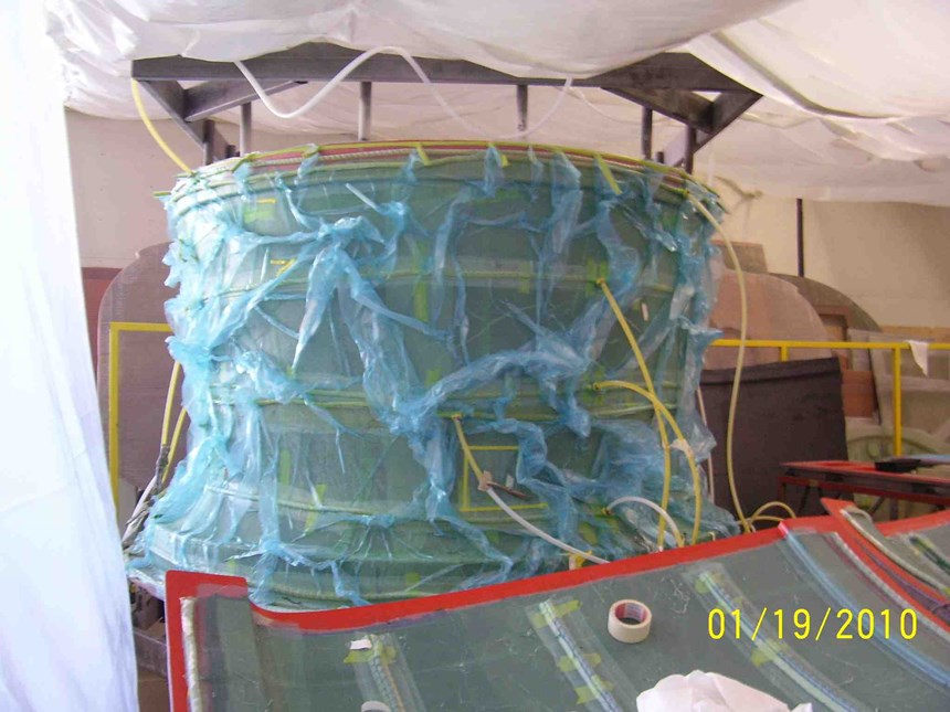
The M10’s two primary structures — the hull and the superstructure — were designed and built separately, but the basic manufacturing steps for each are similar: skin layup and infusion, followed by stiffener integration and infusion (see step photos at right). The hull, however, also features a series of transverse and longitudinal frames to create a “buoyancy box” in the bottom of the craft.
Construction of the hull and superstructure starts with the molds, which were entirely manufactured by EPS Vectorworks. For the molds, Polycryl tooling gel coat from Interplastic Corp. – Thermoset Resins Div. (St. Paul, Minn.) is sprayed on and cured, then backed by chopped strand mat and a low-density foam foundation.
The M10 hull is built using a single-skin biaxial glass woven roving in a vinyl ester matrix. The glass biaxial fabric is sourced from Vectorply (Phenix City, Ala.); the vinyl ester is provided by Interplastic. Kurtis Hopf, senior VP of operations at EPS Vectorworks, says the thickness of the solid laminate in the hull and superstructure is about 5 mm/0.20 inch. The decks and frames feature sandwich construction, consisting of hand-layed glass fiber faceskins (reinforcements from Vectorply) surrounding a PVC foam core from DIAB (DeSoto, Texas). After the hull skin is infused, Vectorworks installs a series of stiffeners, comprising urethane foam overlaid with glass fiber fabric. After the stiffeners are infused, the previously mentioned series of longitudinal and transverse beams are added to create the craft’s buoyancy boxes over the skin and stiffeners. Hopf says the beams comprise DIAB PVC core wrapped with 2-mm/0.08-inch thick glass fiber fabric infused with Interplastic’s vinyl ester. He points out that they are layed up on plywood patterns designed to precisely match the contour of the hull. Beams and skin are subsequently joined with methyl methacrylate adhesive supplied by IPS Corp. (Durham, N.C.). EPS Vectorworks targeted a beam-to-skin gap of 3 mm to no more than 5 mm (0.12 to 0.20 inch) to limit adhesive volume and, thus, minimize the hull’s weight.
The superstructure also features a sandwich construction, but its faceskins are reinforced with impact-resistant Kevlar aramid fiber, manufactured by DuPont Protection Technologies (Richmond, Va.) and sourced through JB Martin (St.-Jean-sur-Richelieu, Quebec, Canada). The faceskins encapsulate a DIAB PVC core, and the assembled materials are vacuum infused.
Vacuum infusion was the process of choice for the majority of the vessel’s structural components, both solid and sandwich construction, because the resulting laminates have high specific strength and the process can be done with a high level of predictability and repeatability. The vacuum system, which for the most part features vacuum pumps provided by Busch USA (Virginia Beach, Va.), was designed based on initial flow modeling by Composites Consulting Group (a DIAB business unit). The vacuum system design and modeling data enabled Vectorworks to achieve part fiber content of 65 to 70 percent by weight. This, in turn, allowed EPS to maximize the payload capacity of the vessel.
After the superstructure and the hull (the latter, with all stiffeners and beams in place) are completed, the superstructure is craned into position on, and attached to, the hull.
Propeller shrouds
The two 2.48m/8.1-ft diameter propellers at the aft of the craft are encased in rigid but lightweight (200-lb/90-kg) composite shrouds, manufactured with a mix of glass fiber- and carbon fiber-reinforced laminate. Construction of each shroud starts with an “apple core” mold over which is laid 0°/90° woven carbon fiber fabric, brand named TC-18-N and provided by JB Martin. The layup is infused with Ampreg 22 epoxy resin supplied by Gurit (Isle of Wight, U.K.). A series of reinforcing ribs for the shroud are fabricated separately, from glass fabric and infused with Ampreg 22. Cured ribs are bonded to the just-infused carbon skin around the apple core mold and taper out from the edge of the shroud to a gradually increasing height at the other end of the shroud. Also fabricated separately is a series of cured, carbon fiber/epoxy composite skins. These are bonded to the outside of the shroud and attached to the ribs to complete the shroud structure.
Finally, the four rudders are attached to the narrowest end of the shroud, running in parallel across the shroud’s rear opening. These rudders, like the ribs on the shroud itself, are made with 0°/90° carbon fiber fabric and infused with epoxy. They’re attached to the shroud via bracketed bearings, and they swivel to change airflow direction to facilitate steering the craft.
All involved with the design and manufacture of these craft agree that one of the greatest challenges of the EPS M10 is the requirement that it be extremely lightweight, yet able to live up to the demands of a harsh marine environment, and the punishment offered by a true military operator. Cutts states, “Fortunately, with an all-infused composite structure, and the ability of EPS Vectorworks to develop a process that is consistent with high fiber ratios, we have managed to keep weight to a manageable level.”
Hopf points to support EPS Vectorworks received from Composites Consulting Group and Interplastic Corp. in development of consistent, high-quality molding processes. “This isn’t rocket science, but the details ... are very important,” he points out, noting, for example, the issue of core edge mating. “You want minimal gaps to avoid racetracking. And you want to make sure the glass is tight in the corners.” Each well-mated edge and well-positioned fabric minimizes resin-based weight. “These are little things, but very important.”
With its manufacturing processes well under control and two M10s out the door, EPS is primed to deliver more, and expand the presence of composites in the global hovercraft community.
Related Content
COMPINNOV TP2 project promotes use of thermoplastics in aerospace
Completed in 2023, COMPINNOV TP2 explored thermoplastic composites, enhancing the understanding between prepregs and production methods to foster the potential for French aerospace innovation.
Read MoreGKN Aerospace, Joby Aviation sign aerostructures agreement
GKN Aerospace will manufacture thermoplastic composite flight control surfaces for Joby’s all-electric, four-passenger, composites-intensive ride-sharing aircraft.
Read MoreCompPair adds swift prepreg line to HealTech Standard product family
The HealTech Standard product family from CompPair has been expanded with the addition of CS02, a swift prepreg line.
Read MoreMFFD thermoplastic floor beams — OOA consolidation for next-gen TPC aerostructures
GKN Fokker and Mikrosam develop AFP for the Multifunctional Fuselage Demonstrator’s floor beams and OOA consolidation of 6-meter spars for TPC rudders, elevators and tails.
Read MoreRead Next
Modeling and characterization of crushable composite structures
How the predictive tool “CZone” is applied to simulate the axial crushing response of composites, providing valuable insights into their use for motorsport applications.
Read MoreCFRP planing head: 50% less mass, 1.5 times faster rotation
Novel, modular design minimizes weight for high-precision cutting tools with faster production speeds.
Read More


.jpg;maxWidth=300;quality=90)


