Size-unlimited OOA composite process enables next-gen system
United Launch Alliance selects Ruag Space for lower cost/improved quality out-of-autoclave manufacture of Vulcan’s composite primary structures.
For the past decade, United Launch Alliance (ULA, Centennial, CO, US) has been a cornerstone of US space industry launch system activities. The Boeing Co. (Chicago, IL, US) and Lockheed Martin (El Segundo, CA, US) formed ULA in December 2006 as a 50/50 joint venture, bringing Lockheed Martin’s Atlas and Boeing’s Delta launch systems together under joint management to ensure reliable, cost-efficient space launch services for the US government and its launch customers.
ULA is now replacing Atlas and Delta with next-generation launch rockets under the Vulcan name. Beginning with the Vulcan Centaur, this new, single family of vehicles will provide the full range of capability currently provided by the combined Atlas/ Delta families, says ULA’s VP of engineering Mark Peller. Further, he adds, “As we retire the Atlas vehicle, it will enable us to retire its Russian-built RD-1 engine.” The primary engine option for Vulcan is the BE-4, built by Blue Origin (Kent, WA, US), with the AR1 engine, built by Aerojet Rocketdyne (Sacramento, CA, US), as a backup.
Vulcan Centaur (first flight scheduled for 2019) is designed to exceed the Atlas V’s capability, offering a single booster stage, a high-powered Centaur second stage and either a 4m- or 5.4 m-diameter payload fairing. “Up to four solid rocket boosters augment the lift-off power of the 4m configuration, while up to six boosters can be added to the 5m configuration,” ULA reports. The Vulcan ACES (Advanced Cryogenic Evolved Stage) heavy lift vehicle will follow, scheduled for first flight in 2023. ACES will replace the Centaur second stage and its propellant will be cryogenic. That means it must house the tanks and piping that handle the ultra-cooled (-150°C) liquid oxygen and liquid hydrogen.
Peller points out that composite materials have been selected for the Vulcan primary structures to improve the quality of the product and to reduce cost. The key to the cost reduction component is a practical out-of-autoclave (OOA) process developed by ULA’s manufacturing partner, Ruag Space (renamed to Beyond Gravity).
ULA/Ruag strategic partnership
Headquartered in Zurich, Switzerland, with 10 sites worldwide in Sweden, Finland, Austria and the US, Ruag Space is making OOA its baseline for manufacture of composite structures for launch vehicles, including payload fairings for the European Space Agency’s (ESA, Paris, France) heavy-lift launchers Ariane 5 and Ariane 6, and its smaller Vega configuration, as well as ULA’s Atlas V and the Vulcan (also see Learn More located under “Editor’s Picks” on the top right).
Matteo Rendina, manager of product engineering for Ruag Space, explains the reasoning behind the company’s OOA strategy. “Normally, the limits for manufacture of composite products are established by the size of the equipment laying down the carbon fiber — for example, a tape laying or fiber placement machine,” he notes. “At Ruag we don’t have this limit,” he points out, noting, “We can manufacture any size the customer needs because we mastered production methods that are not linked to these types of automated machines. This was a strategic decision we have taken.”
Disadvantages of this approach are the need for operator assistance in a semi-automated operation, and a slower production rate than a fully automated system. Ruag’s analysis, however, shows that given the relatively low production rate, these disadvantages are well offset by the advantages of parts consolidation, low equipment cost, and nearly unlimited size capacity.
As part of the ULA/Ruag strategic partneship, announced in July 2015, Ruag will establish a composites production capability within ULA’s Decatur, AL, US, factory and manufacture new composite structures for ULA’s Vulcan rocket, and manufacture 5.4m payload fairings and 400-series interstage adapters for ULA’s Atlas V (Ruag has manufactured Atlas V components in Switzerland for several years).
Ruag is expected to begin work mid-2017 in Decatur. Hardware delivery for Atlas V is planned for late 2019. Hardware development and qualification of the new Vulcan composite component structures is planned through mid-2020, with first delivery of Vulcan components later that year.
High-performance without an autoclave
Ruag will build Vulcan’s payload fairing, interstage adapter and heat shield. All will be manufactured by the same OOA process, Rendina says, but the material systems and the design details for the laminate layup, sandwich core and thermal protection system will vary among them. The interstage connects the first and second stages of the rocket. A single 360° structure, 4m high, the interstage is built up and cured in one piece. It measures 5.4m in diameter at its base, but is tapered on the forward end to interface with the smaller diameter second stage. The heat shield, at the base of the rocket, is also 5.4m in diameter.
The Vulcan’s 5.4m-diameter payload fairing, which will be built in three lengths (20.7m, 23.5m and 26.5m), is an excellent illustration of the utility of Ruag’s process. Payload fairings are made in two longitudinal half-shells, each comprising a cylindrical shape joined to an ogive shape at the nose cone. During launch preparation, the two half shells are fastened together around the spacecraft or other payload, enclosing it for its protection during the first phase of flight. At a specified point, after clearing Earth’s atmosphere, the fairing is separated and jettisoned from the launch vehicle, thus permitting the later separation of the spacecraft for entry into orbit.
A huge advantage of Ruag’s OOA composite construction for the payload fairing is that each fairing half shell — incorporating the cylindrical and ogive sections — can be made in a single piece that consolidates all parts: inner and outer skins, honeycomb sandwich core, and exterior thermal protection system. “These are all cured together as a complete sandwich structure in order to obtain the required mechanical properties,” Rendina explains.
Material preparation
The first step of Ruag’s OOA process is material preparation. For the fairing, a woven carbon/glass prepreg fabric supplied by Solvay Specialty Polymers (Woodland Park, NJ, US), featuring standard-modulus (230 GPa) T300 carbon fiber from Toray Industries Inc. (Tokyo, Japan) and S-glass from AGY Holding Corp. (Aiken, SC, US) in an unidentified Cytec resin matrix. Other fibers were considered, but “at the end of an exhaustive trade-off study, we confirmed the use of the heritage T300 fiber, which had already been used successfully in both Ariane 4 and Ariane 5 payload fairings,” Rendina says.
A high-strength carbon fiber would not justify its higher cost, he points out. Although a high-tensile-modulus/high-strength fiber would permit a thinner laminate and that would be an advantage in some applications, with parts of this size, a certain skin thickness is required to ensure fairing stability and resilience.
Ruag selected a 0°/90° woven fabric with a combination of carbon fiber woven in the axial and circumferential direction, and some glass fiber in the 90° direction. In some areas, in accordance with the design specification, the 0°/90° fabric is applied at a 45° angle, to obtain a quasi-isotropic 0°/90°/±45° laminate. The carbon fiber gives the required stiffness in both directions for stability and limited deflections, Rendina explains, while the placement of glass fibers in the circumferential direction gives the laminate a greater degree of flexibility due to a lower modulus of elasticity (less stiffness) than it would have with carbon fiber reinforcement alone, which proves helpful when the two halves must separate with sufficient clearance from the launch vehicle during flight.
Although the resin could not be identified, it was selected based on its oven-cure compatibility, and the fact that it has a Tg high enough to reduce the amount of thermal protection necessary on the outside of the fairing. “The external thermal protection reduces the thermal heat flux acting on the composite sandwich during atmospheric flight. This helps protect the sandwich structure from excessively heating up, thus holding the operating temperature of the sandwich sufficiently below the Tg,” Rendina explains. Further, its outlife permitted time enough to layup such a large part.
Layup of the part
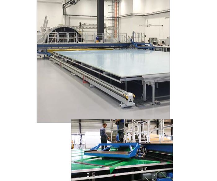
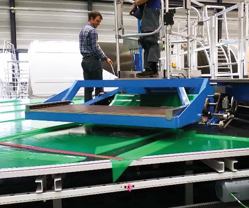
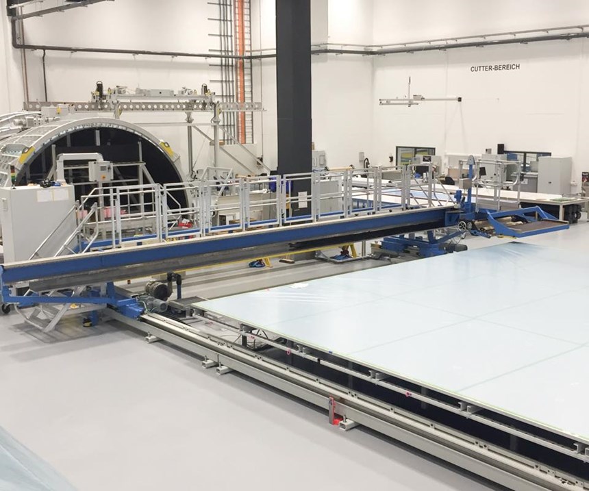
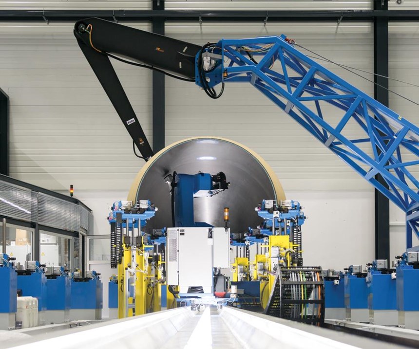
Solvay provides the prepreg fabric in rolls of about 1m wide. The prepreg roll is installed on Ruag’s semi-automated fabric lay-down machine, which was built to Ruag’s specifications by Eugen Ostertag GmbH, now Eugen Ostertag Automation (Laichingen, Germany). The prepreg fabric is automatically rolled out onto a flat tooling table for layup of the inner skin, guided by a laser projection system from Virtek Vision International (Waterloo, ON, Canada). For areas of part geometry not manageable by the machine, which simply rolls out prepreg fabric in 1m widths and cuts it along the roll line, such as when off-angle orientations are called for, an operator manually trims the fabric at the edges (Steps 1 & 2).
The layup for the payload half-shell is subject to intermediate consolidation to remove any entrapped air and avoid potential voids in the laminate, using a proprietary method. Rendina says Ruag achieves an average void content of slightly more than 1%.
After layup and compaction of the inner skin, the skin is transferred from the table onto a male bonding mold by a dedicated lifting and transfer jig, a vacuum-assisted tool designed by Ruag that grips the skin along two sides and along its middle (Steps 3, 4 & 5). The inner skin of the ogive-shaped nose cone is laid up with the same prepreg manually, directly over the ogive male bonding mold, adjacent to the inner skin of the cylindrical section.
An aluminum honeycomb core, provided in blocks by Hexcel (Stamford, CT, US), is machined to the required thickness, expanded to the desired shape and bent on a dedicated tool to the corresponding radius for the cylindrical and ogive sections of the fairing. The honeycomb is then manually arranged over the cylindrical and ogive inner skins on the mold.
The outer skin of the cylindrical section of the fairing is then laid up in the same manner as the inner skin, and positioned over the honeycomb core by means of the lifting and transfer jig.
The outer skin of the ogive section is layed up manually on a dummy mold. Thermal protection in the form of a compressed cork provided by Amorim Group (Mozelos VFR, Portugal), is positioned over the layup. The part is transferred to the bonding mold by means of hundreds of small vacuum pads arranged on another dedicated jig (Step 6). Lastly, a layer of the cork is arranged over the outer skin of the cylindrical section. The cork, bonded on the outside skin of the fairing’s composite sandwich protects the sandwich from the aerodynamic frictional heat generated on the fairing’s exterior. The complete part sandwich layup is now ready for vacuum bagging and cure.
Curing process
Curing is performed once for each fairing half shell. “The end product of the cure is a composite shell, thermally protected, on which all the subsystems required by the payload fairing will be assembled,” Rendina points out. Those are installed mainly on the inside of the fairing (instrumentation, venting system, acoustic protection system), but some are placed on the main structural path (separation systems) and some on the external side of the fairing (interfaces to the ground).
Each fairing half shell is cured in a large oven (Step 7) supplied by Luterbach AG (Hildisrieden, Switzerland) according to a specific time and temperature profile established “after investigating the effect of different parameters on the resulting material performance,” Rendina says. These include the viscosity and Tg (high) of the resin; the application of a vacuum level that best facilitates air evacuation and achieves thorough consolidation; and realization of a homogeneous cure that curtails hot and cold areas, to limit part distortions.
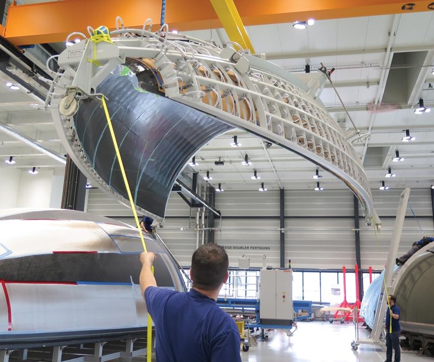
To ensure the latter, Ruag has conducted extensive computational fluid dynamics (CFD) analyses on the air circulation inside the oven to ensure even temperature distribution over the entire part. After cure, the fairing shell is lifted from the mold by a lifting jig, also equipped with vacuum pads, and transferred to the next station for nondestructive testing.
Ruag has to guarantee the quality of each article delivered to its customers, Rendina says. But to accomplish this cost-effectively, testing must be limited. The company validates its guarantee in several ways. First, it confirms quality and consistency during production of each part. This is especially important during cure. “We diligently pursued, and achieved, a curing process with sufficiently large boundaries from the nominal curing path. We are confident in now having sufficient control parameters to justify the quality of the structure.”
Acceptance tests are, therefore, limited to nondestructive inspection (NDI) of the complete shell after cure, plus visual inspections after each postcure operation. NDI is accomplished via a 200-kHz, air-coupled ultrasonic through-transmission with scan resolution adjustable between 0.1mm and 50mm. Scan time is about 20 min/m2. Ostertag supplied the NDI system, which is carried on a robot from Robot Technology GmbH (Grossostheim, Germany). “Further, sacrificial test panels are manufactured together with each composite shell, and samples can be cut out of these panels in-process if material characteristics need to be measured,” Rendina adds. After acceptance, the part is ready for transfer to the Horizontal Integration Station (HIS).
Postcure operations
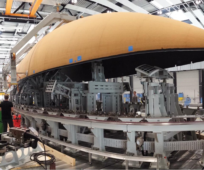
Before the fairing is mounted on the HIS, two types of separation systems are installed onto this large tool. The separation systems are necessary during flight to separate the fairing horizontally from the launch vehicle, and for separating the payload fairing shells vertically so they can be jettisoned away. When the composite fairing shell is installed into the HIS (Step 8), matched holes are drilled in the composite shell and the separation system, and they are connected. (The Ruag separation system consists of hardware that is attached to the fairing to keep satellites or other payloads safely attached to their fairings during the tough journey to orbit and then with precision causes the fairing halves to separate at the right time and delivers the precious loads in orbit with the specified relative velocity, roll and/or spin.)
Next, the fairing sandwich structure edges are trimmed, and other drilling is done for equipment that will be attached afterward. No further machining of the structure’s surface is necessary, because it is manufactured and cured to net shape. “We do not do any correction of the geometry after the curing process,” Rendina confirms.
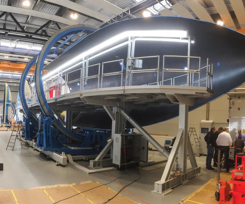
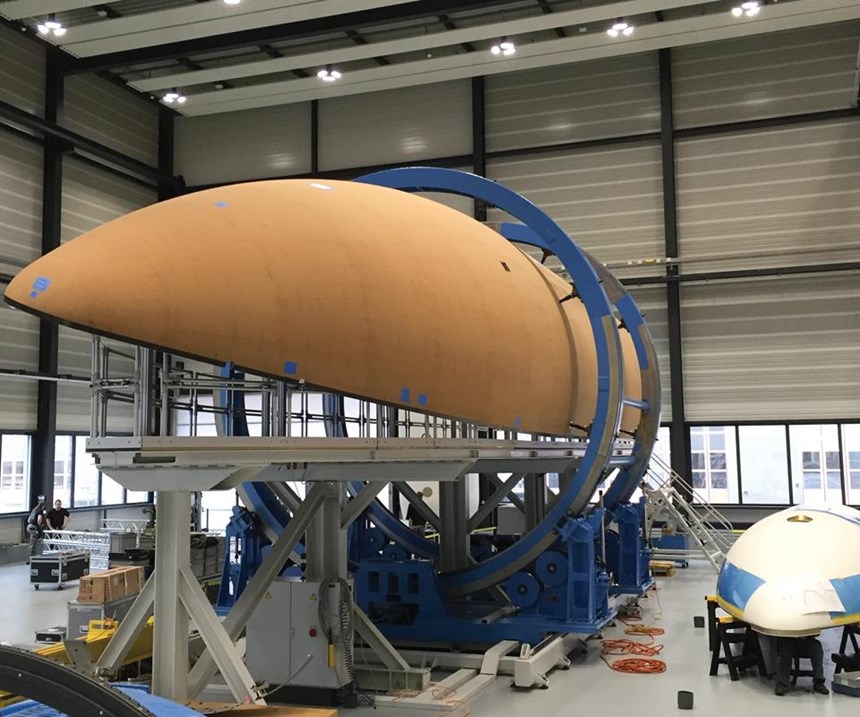
The fairing is then moved to the machining station (Step 9), where access doors, venting devices and other mission-specific equipment is installed. Designed for best ergonomic operation, the machining station permits rotation of the fairing so the operator always works in a safe and comfortable position.
The finished fairing is painted white for thermal reasons, Rendina says. “The launch vehicle stays on the launch pad for many hours, sometimes under sunlight, and it gets very warm, so we need the white color to keep the ground temperature of the fairing structure as low as possible.”
A practical compromise
Today, the volumes demanded in commercial aerospace and, especially, automotive production, are dictating that composites manufacturers who serve those markets pursue greater automation and necessarily, therefore, face greater difficulty in meeting both part performance and customer cost goals. But ULA and Ruag’s flexible, semi-automated OOA compromise between the extremes of hand-laid, autoclaved prepreg and fast but size-limited automated tape laying or fiber placement avoids artificial limits and better fits space industry realities. For the small volumes typically contracted in the space market, it’s an efficient process that permits builds of launch vehicles beyond conventional bounds yet does much to keep costs within customer boundaries.
Related Content
Nine factors to consider when designing composites cure tooling
Gary Bond discusses the common pitfalls and compromises when designing good cure tooling and their holistic significance for a robust composite production process.
Read MoreComposite sidewall cover expands options for fire-safe rail components
R&D project by CG Rail explores use of carbon fiber-reinforced thermoplastics and recycled manufacturing scrap to meet fire safety, weight and volume targets.
Read MoreOptimized approach to predict delamination failure in CFRTP structures
ARRK Engineering and Mitsui Chemicals improved delamination prediction accuracy to help optimize absorbed energy/failure load for an overmolded TAFNEX CF/PP UD tape bumper beam.
Read MoreOptimizing a thermoplastic composite helicopter door hinge
9T Labs used Additive Fusion Technology to iterate CFRTP designs, fully exploit continuous fiber printing and outperform stainless steel and black metal designs in failure load and weight.
Read MoreRead Next
Composites role in the emerging space industry
A decade since NASA opened extraterrestrial space to potential use as a commercial industry workplace, in this month's issue, CW traces the role composites have played in public/private progress toward that goal.
Read MoreAll-recycled, needle-punched nonwoven CFRP slashes carbon footprint of Formula 2 seat
Dallara and Tenowo collaborate to produce a race-ready Formula 2 seat using recycled carbon fiber, reducing CO2 emissions by 97.5% compared to virgin materials.
Read More“Structured air” TPS safeguards composite structures
Powered by an 85% air/15% pure polyimide aerogel, Blueshift’s novel material system protects structures during transient thermal events from -200°C to beyond 2400°C for rockets, battery boxes and more.
Read More
