Sportfishing yacht: Infusion optimized
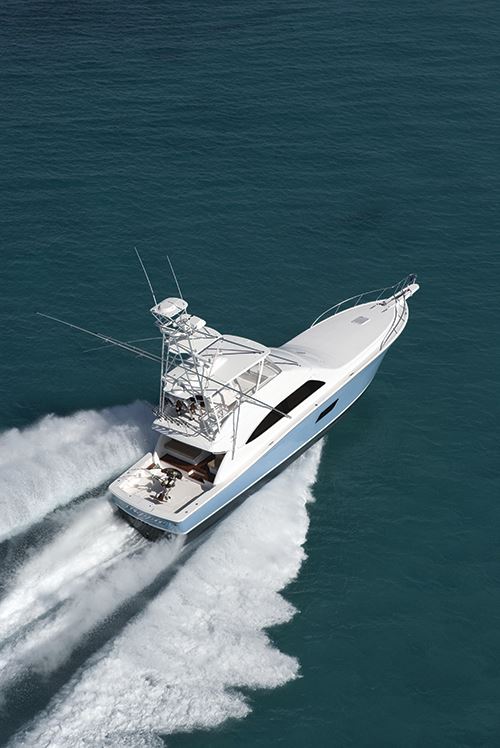
This well-loved deepsea fishing brand has moved from Miami to a new facility, and to a state-of-the-art resin-infused laminate for its Bertram 64.
The venerable Bertram Yachts brand was born when founder Dick Bertram decided to build on his well-earned reputation as an ocean sailor and as the victor in the 1960 Miami-to-Nassau powerboat race. Bertram handily outdistanced all in the demanding, eight-hour open water speed contest, with a 31-ft/9.4m “deep-V”-hulled wooden boat called Moppie, after his wife’s nickname. By 1961, he was molding a fiberglass version of Moppie, dubbed the Bertram 31, in the style of a sportfishing boat, with a wrap-around cabin and flybridge, Some marine insiders still call it “the top sportfishing boat on the planet,” and a fleet of nearly 13,000 Bertram sportfishers exist, worldwide.
For Bertram and the rest of the marine industry, the Great Recession brought great change. Although annual retail powerboat sales are still far below the prerecession high-water mark of 300,000 units, they are rising — a resurgence reflected in increased activity at many boatyards. After building boats for more than 50 years in Miami, Bertram Yachts is riding this wave of change at a new facility in Merritt Island, Fla. “We’re celebrating one year at our new site,” says Alton Herndon, president of Bertram and a marine industry leader, “and are moving forward with optimized composite designs and improved fabrication to make our well-known sportfishing boats even better.”
Part of the Ferretti Group since 1998, Bertram builds large, sturdy and seaworthy performance powerboats and sportfishing vessels that are often seen in use at deepsea fishing tournaments. The move from the company’s Miami airport site to Merritt Island came about because the former was simply too small: “Any vessel larger than 60 ft in length had to be launched at high tide, since our slip was very tight,” Herndon explains, “and when we began offering the 80, the only option was to hire a 500-ton crane and literally lift the boat over the building into the water.” Further, the heights of larger models exceeded the building’s inside clearance, so final construction was done outside, in the weather. With access to both the Intercoastal Waterway and the Atlantic, the Merritt Island site boasts two larger buildings, 37 acres for expansion and, Herndon points out, a local workforce with deep composites-fabrication experience.
Open molding to infusion
A new location, however, was just the beginning. Bertram also left behind open molding and moved to vacuum-assisted resin infusion, which it had previously used only for smaller parts, for all of its manufacturing: “We were looking to improve repeatability and increase strength with a re-engineered composite laminate design,” says Robert Ullberg, Bertram’s VP of product development and engineering. To that end, and to improve their “comfort level” with an all-infusion approach, Ullberg and Herndon turned to boat manufacturer Vectorworks Marine and its naval architecture/design subsidiary Vectorworks Naval Engineering (Titusville, Fla.) to collaborate on infusion-optimized laminate designs.
Vectorworks, in turn, brought in the Composites Consulting Group (CCG, DeSoto, Texas), an independent composites design company within core supplier DIAB Group (Laholm, Sweden), as well as fiber reinforcements manufacturer Vectorply Corp. (Phenix City, Ala.) and resin systems suppler Interplastic Corp. – Thermoset Resins Div. (St. Paul, Minn.).
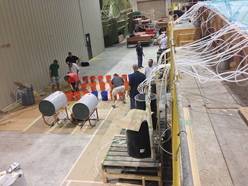
“CCG’s expertise in infusion flow modeling and Interplastic’s resin formulation experience were key to that ‘comfort level’ that we were going for,” says Vectorworks’ Kurt Hopf, senior VP of operations. “We have a longstanding, 20-year relationship with these partners, which helped us assemble a productive and competent team for this project, together with Bertram.” Adds Bill Kulenguski, Vectorworks engineering manager, “It is a very scary moment when you’ve got many drums of catalyzed resin around you and it’s time to infuse expensive reinforcements — we wanted to ensure the best outcome.”
Vectorworks began by developing a new laminate design for a customer’s Bertram 64, a model previously produced via hand layup and manual wetout with rollers. At 64 ft/19.7m long, with a beam of 18.2 ft/5.6m and a draft (the hull depth below the waterline) of 5.5 ft/1.7m, its outward appearance and major systems could not deviate from Bertram’s legacy design. And a reputation as rugged and seaworthy in any weather dictated that all parts of a Bertram vessel be very solid. For example, the soles (deck panels) that span the supporting bulkheads to form the vessel’s floors had to exhibit a minimum 300:1 length-of-span-to-deflection ratio.
The design, then, demanded special care. “We developed the vessel’s laminate zones to meet the anticipated global loads as defined by RINA Services SpA (Genoa, Italy), a naval vessel classification society,” Kulenguski recalls. RINA’s Rules for Classification of Pleasure Yachts predict the overall loads, accelerations and pressures based on the vessel dimensions, dead-rise angle, displacement, draft and velocity. RINA rules were cross-checked with loads and design criteria from the International Organization for Standardization’s (ISO, Geneva, Switzerland) ISO 12215 standard “Small Craft – Hull Construction and Scantlings.” Use of classification rules provides for independent review and quality control of the engineering design and construction. Practically, it also “reduces insurance rates,” he adds, “and if the vessel is going to be used for commercial charter in the U.S., it helps facilitate review and inspection by the U.S. Coast Guard.” That said, Kulenguski and Hopf stress that classification society rules are no substitute for sound, independent engineering judgment. Ultimately, he asserts, “we took a ‘first principles’ approach in order to evaluate the structure in terms of safety factors on stress and strain.”
Laminates to match the loads
Hull laminate thickness was a key parameter. The hull has to withstand the anticipated bottom hydrodynamic pressure, as well as other loads that include boat storage considerations — keel blocks, lifting strap positions — and grounding loads created by the propellers’ supporting struts. Kulenguski explains that overall loads include longitudinal and vertical bending moment and shear force (“hogging” and sagging conditions). Local loads, such as hull pressures, are dependent on longitudinal position along the hull and panel size — that is, the areal extent of a hull segment located between stringers and transverse frames. Slamming effects are included in the pressures, primarily mid-ship and forward. Deck and superstructure pressures are based on location: “RINA assumes top speed of 40 knots/46 mph at maximum displacement in a sea state with 4m/13-ft wave height.”
Further, the arrangement and positions of transverse frames and bulkheads in the new design was constrained by the layout of the original cabin and staterooms, which was to be preserved unchanged. So bulkheads and other structures in the infused design had to be positioned in such a way that the interior walls would conceal them. Placement of stringers along the hull’s length was dictated by the locations of engines, tanks and gyrostabilizers, which also were unchanged from the 64’s legacy design.
Developed in-house, Vectorworks’ design spreadsheets reflect the classification societies’ rules and Bertram’s own experiential rules. The company employs Vectorlam Cirrus software, from Vectorply, for material trade studies and for developing “smeared” laminate properties, says Kulenguski. (Smearing is designer parlance for combining all of the material properties of a laminate stack together to obtain a single value.) “Vectorlam has a good composite materials physical properties database, and the software has proven to be pretty accurate when you compare it to destructive test data.”
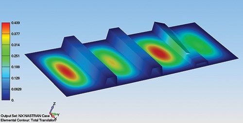
To test the spreadsheet assumptions and put together ply-by-ply reinforcement stackups for the hull and decks, Vectorworks did finite element analysis (FEA) using NX Nastran with FEMAP, supplied by Siemens PLM Software (Plano, Texas). The FEA verified the Vectorlam data and first-ply failure, and identified problem areas, adds Hopf. It also gave Vectorworks the ability to model adhesively bonded joints and solve for the deflection and shear stress in the adhesive itself. The FEA also enabled a ply-by-ply look at stress and strain within the stack, which is particularly important when checking the gel coat safety factor. “Since gel coat is a relatively brittle material, we wanted a design that minimized strain on that outer cosmetic skin, with less than 1 percent elongation in the vessel,” he adds.
A key aspect of the 64’s design was Vectorworks’ simultaneous CAD modeling along with the structural model. A complete 3-D model using Unigraphics NX (now Siemens PLM Software NX) was prepared that included all of the vessel’s mechanical, plumbing and electrical systems fully integrated with the laminate design, a new design strategy that other boatbuilders are now starting to employ. This ensured that potential issues, such as equipment mounting points or hull penetration, were accounted for with extra fabric reinforcements or other structural modifications. “This kind of planning integrated into the laminate design really streamlines the construction process,” says Hopf. All aspects of the laminate and CAD design were discussed with Bertram during the process, adds Kulenguski: “We worked out with them what could, or couldn’t, change from the legacy layup.” Although Bertram elected to use its existing composite mold for the first infused 64 hull, Vectorworks will produce the plugs and molds for future projects, using its CAD design data.
Infusing the new layup
The design precipitated a big manufacturing change for Bertram’s monolithic hulls, from a solid to a mostly cored sandwich construction. Kulenguski points out: “The move to infused laminates gave Bertram the opportunity to switch to a cored hull. The beauty of infusing a sandwich construction is that you can rest assured that the core-to-skin interface is 100 percent complete and void-free, minimizing the risk that every manufacturer of cored laminates faces.”
Ultimately, the design generated a variety of laminate zones, based on the local loads and panel sizes: Hull laminate thicknesses range from 3/8-inch/10-mm to 2-inch/51-mm cored sandwich, with the majority at 1.5-inch/38-mm thickness. Thanks to the lower weight of the cored bottom, Vectorworks was able to reduce hull internal structure, since the cored panels have a much higher modulus and enable a larger panel size. Further, the main deck and flybridge are lighter, consisting primarily of 1.25-inch/32-mm cored sandwich construction.
When the laminate design was in place, materials were specified for the infusion. E-glass reinforcements, obtained through distributor Composites One (Arlington Heights, Ill.), included unidirectional as well as biaxial and triaxial noncrimp fabrics manufactured by Vectorply. Interplastic supplied low-viscosity MVR 8075 vinyl ester resin, formulated for infusion, with high heat-distortion temperature (HDT) characteristics. Also specified was DIAB H100 1-inch/25-mm thick closed-cell foam core material for the hull bottom, and H80 1.5-inch/34-mm thick foam core for the hull sides. The four longitudinal stringers contain high-density foam core, covered with the noncrimp fabrics. To reduce laminate print-through as much as possible, Soric from Lantor Composites (Veenendaal, The Netherlands) was specified as a print barrier.
“Vinyl ester resin, while it provides superior physical properties, generates a fair amount of exotherm during cure and exhibits higher shrink than some other resins,” explains Hopf. “The Soric material as a first layer in the mold behind the gel coat helps prevent print-through and guards the gel coat against the resin effects.” For this first infused hull, Vectorworks specified a clear gel coat, supplied by Ashland Performance Materials (Dublin, Ohio) on the hull bottom, so that it could be readily inspected after cure to validate infusion results.
A number of test panels were fabricated per the design and infused, then destructively tested, not only to verify the Vectorlam and FEA modeling, but also to compare infused properties against Bertram’s legacy open-molded laminate structure. According to Kulenguski, panel testing showed “very accurate” agreement of mechanical properties between the model and actual cured laminates, at 68 percent fiber content, with good panel-to-panel repeatability of properties. “And, the infused panels met or exceeded the legacy design, at a lower weight,” he adds.
Infusion expert Belle Blanding, one of CCG’s senior consultants, conducted infusion flow modeling. Polyworx (Nijverdal, The Netherlands) software enabled virtual infusion to determine best placement of resin runners, and injection and venting ports, and provided risk-free information on how the resin would move through the modeled laminate, explains Blanding. Concurrent with the flow modeling, Blanding also used Vectorwork’s test panels for basic Darcy’s Law permeability flow tests, to help confirm the Polyworx results: “This was a complex infusion to design, because of the many different laminate zones and the bends and twists in the stringers.” The team opted to co-infuse the longitudinal stringers along with the hull laminate, an innovative approach that is gaining traction in the industry. “It makes it possible to get an integrated laminate with one cure cycle, and we were confident that the stringers would bond completely to the hull,” Blanding recalls, pointing out, “It avoids a separate, time-consuming and labor-intensive bonding step.”
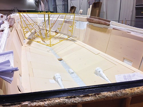
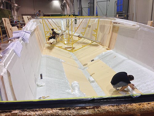
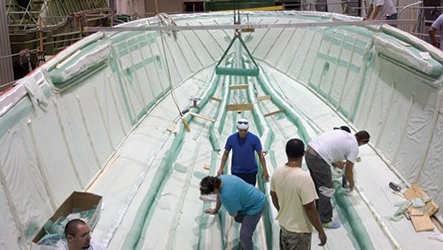
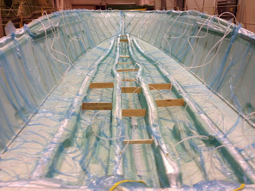
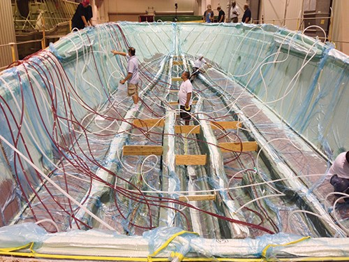
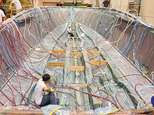
With infusion planning underway, the team layed up the fabric-and-core “dry stack” and then CCG’s process specialist, Dean Callander, supervised application of peel ply and the elements of the infusion “manifold” — the arrangement of resin feed lines, runners and vacuum ports into the hull layup, based on Blanding’s Polyworx model runs. In all, more than 50 vacuum and resin flow lines, and two work days, were required for the manifold setup.
To ensure complete wetout of the complex longitudinal stringers, the manifold included vacuum ports along the stringer tops, where the heaviest stringer laminates were located. Blanding and Callander say this approach makes stringer infusion independent of, yet simultaneous with, the hull infusion. Otherwise, stringer infusion would follow hull infusion and extend total infusion time. Sacrificial flow media, Greenflow from Airtech International Inc. (Huntington Beach, Calif.), was placed along the sides of the stringers to facilitate resin flow along the stringer lengths. After all the manifold elements were placed, the entire hull was vacuum bagged and sealed.
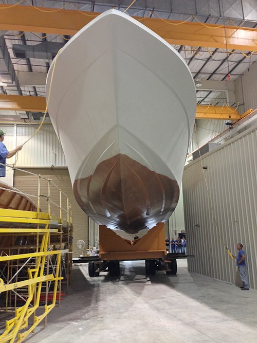
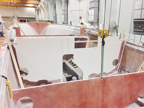
When all was ready, the infusion took place on Nov. 8, 2013, and took about three hours. Interplastic representatives were on site to monitor resin mixing and initiator addition. After a room-temperature cure of several weeks, during which internal bulkheads and deep floors were installed, the hull was demolded on Nov. 26, using an overhead crane. “The clear gel coat gave us a good look at the infused laminate to validate the model and manifold,” Hopf reports. “The laminate looks absolutely perfect — we couldn’t have asked for anything better!” Given that outcome, all Bertram models will be made in this manner.
Infusion of the main deck and smaller flybridge decks was undertaken in December. And as CT went to press, hull build-out continued, including bonding of interior soles and flats.
“Moving forward,” Herndon concludes, “we are ensuring the Bertram legacy by employing new manufacturing innovations and continuous improvement, and making every build better than the one before.”
Adds Hopf, “Being able to bring this team together, with whom we have successfully completed so many vessels … was a tremendous boon to the project.”
Related Content
Pittsburgh engineers receive $259K DARPA award for mussel-inspired underwater adhesion
The proposed META GLUE takes inspiration from hydrogels, liquid crystal elastomers and mussels’ natural bioadhesives to develop highly architected synthetic systems.
Read MoreAdhesives, material solutions promote end market versatility
CAMX 2023: Rudolph Bros. and Co. highlights its role as a prominent specialty chemical distributor and solutions provider with a display of high-performance adhesives, sealants, materials and more from well-known manufacturers.
Read MoreHeat-activated foaming core rapidly achieves net-shape 3D parts
CAMX 2024: L&L Products exhibits its InsituCore foaming core structural technology, which can be used to create foam core composites minus machining or presses, as well as the Phaster A K-700, a rapid-cure adhesive.
Read MoreBelzona composite wrap restores corroded carbon steel pipeline
Two-part epoxy paste, epoxy structural adhesive, composite wrap and anti-corrosion coating prevent environmental and economic loss for customer.
Read MoreRead Next
“Structured air” TPS safeguards composite structures
Powered by an 85% air/15% pure polyimide aerogel, Blueshift’s novel material system protects structures during transient thermal events from -200°C to beyond 2400°C for rockets, battery boxes and more.
Read MoreDeveloping bonded composite repair for ships, offshore units
Bureau Veritas and industry partners issue guidelines and pave the way for certification via StrengthBond Offshore project.
Read MoreVIDEO: High-volume processing for fiberglass components
Cannon Ergos, a company specializing in high-ton presses and equipment for composites fabrication and plastics processing, displayed automotive and industrial components at CAMX 2024.
Read More

