Unidirectional composite axial tensile specimens
Dr. Don Adams explains why the design of tensile test coupons is more art than science, and explains the implications of that art for testing accuracy.
Intuitively, we know that a "simple" tensile test is the most fundamental of all mechanical property tests. It tells us how strong and how stiff a material is, and for most essentially isotropic materials, such as metals, the tensile properties are a good indicator of the overall mechanical response. While we should realize that with composites we cannot make a similar inference about other mechanical properties, such as compression and shear, from tensile information, our conditioned response is to try to do so. As a result, there is always an interest in tensile testing.
Generally, the strongest material in a class is usually the most difficult to test for tensile properties. Composite materials are no exception, and the axial loading of a unidirectional composite presents the greatest challenge. (It is debatable whether one should even attempt a tensile test on a unidirectional composite, given the difficulties encountered, but that is a topic for another time.¹ See end note.) This discussion will concentrate on developing a method to meet this challenge, assuming that we then will be able to test other laminates successfully using similar, or simpler, techniques.
The greatest challenge is gripping the unidirectional composite specimen without introducing unacceptable stress concentrations. Typically, grips are clamped onto the specimen ends, thus transferring the applied tensile force via shear at the specimen surfaces into tensile stresses within the specimen. Assuming that the composite is strong, the required clamping forces can become significant. The issue then is how to minimize these required clamping forces, and/or keep them from degrading the measured tensile strength of the specimen.
One approach is to make the specimen as thin as practically possible while still keeping it representative of the material. Thus, unidirectional composite axial tensile specimens are often on the order of only 1 mm (0.040-inch) thick. Note that specimen width is not a factor because both gripping area and applied force vary in direct proportion to specimen width.
Another approach is to make the grip length longer so that the clamping force is distributed over a larger area. But commercially available grips are of limited length as it becomes increasingly difficult to grip the specimen uniformly as length increases. A commonly used grip of 100 kN (22 kip) capacity typically has a grip length of about 63 mm (2.50 inches). Some are even shorter. Incidentally, available grip width also is limited. For example, a typical width for the grips referred to above is about 45 mm (1.75-inches). This is because it also becomes more difficult to uniformly grip a specimen as its width increases.
Given these limitations, it is always desirable to eliminate, or at least minimize, the stress concentrations induced by the grips. A popular method is to cushion the grip forces by using pads at the specimen ends. These end tabs may be bonded to the specimen, thus transferring the shear forces through the adhesive, or simply clamped in position, relying on friction to transfer the shear forces.
Currently, bonded tabs are more popular, although not necessarily better1, and will be the focus here. They are very effective in cushioning the gripping forces, and protecting the specimen surfaces from abrasion. And once bonded in position they stay in place. They do, however, induce a new source of stress concentrations -- those associated with the discontinuity created at the gage length ends of the tabs. One approach is to reduce the abruptness of the discontinuity by tapering the tabs. ASTM D 30392 recommends that the taper angle be >=5°. Of course this means that the taper angle can be almost anything. A 5° taper and two other commonly used taper angles are indicated in Fig. 1, a 90° taper implying no taper at all, that is, square tabs. In fact, the taper angle can be greater than 90°, although benefits have not been demonstrated.
|
Some standards, particularly in Europe3; and Japan,4 recommend square tabs. This suggests some uncertainty among testing experts about the technical importance of tab taper angle. There may be other factors that offset the advantages of using a particular taper angle. It's also possible that the angle doesn't matter much. As can be seen in Fig. 1, the lower limit taper of 5° is less practical, since it is more difficult to machine such a shallow angle on the tabbing material and more difficult to clamp the tabs against the specimen during adhesive bonding, but it certainly can be done. |
The "square tab" philosophy arises from the fact that during tensile loading, tab ends tend to curl away from the specimen, inducing through-the-thickness stresses which potentially can peel off the surface layers of the specimen, thus weakening it.1 Square tabs are stiffer and thus more resistant to curling. Also, square tabs can be gripped right up to their ends, further inhibiting curling, while tapered tabs obviously cannot be. Highly tapered tabs, on the other hand, are very flexible. When they curl they do not necessarily induce high through-the-thickness stresses in the specimen. That said, the intermediate 30° taper tabs shown in Fig. 1 -- which appear to represent a near worst-case scenario based on the above discussion -- are used successfully as well. This all suggests that tab taper angle, in fact, really doesn't matter that much.
The evidence tends instead to support the logical conclusion that compliant tabs perform better than stiff tabs. The limiting condition is that soft tabs have to be strong enough to carry the shear stresses as they are transferred from the grips into the specimen, and softer materials tend to be weaker. For example, glass fabric/epoxy tabs represent a good balance between low stiffness and reasonable shear strength. Tabs with 0°/90° fabric orientation are most commonly used, but a +/-45° orientation is often recommended, because it is softer still. Aluminum tabs, although several times stiffer, are sometimes specified, but are probably a second-best choice. Also, greater care is required when adhesively bonding aluminum because of the oxide surface layer that quickly forms. And to confuse the issue, ASTM D 3039 notes that steel tabs (three times stiffer than aluminum) "have reportedly been successfully used." At least, steel tabs bond more easily than aluminum. The ASTM standard also comments that tabs fabricated of the same material as the specimen "have reportedly been successfully used." But this also is contrary to the previously stated desire to have the tabs be as compliant as possible. Since the specimen material may not have shear strength adequate for use as tabs, many unsuccessful attempts also have been reported.
If compliant tabs are desirable, then a compliant adhesive is desirable as well for the same reasons. Since the stiffness values of most polymeric adhesives are somewhat similar, the specific choice is more often dictated by which has the higher shear strength, a property that varies considerably from one adhesive to another. And since typical adhesives are six to eight times more compliant than the glass-fabric/epoxy tabs suggested above, a thick bond line is beneficial. However, thin bond lines are stronger and thus, once again, a compromise must be made. A 0.1-mm to 0.5-mm (0.005-inch to 0.020-inch) thick bondline is reasonable for many adhesives.
The current state of affairs is summarized best by the following quote from ASTM D 3039: "Design of mechanical test coupons, especially those using end tabs, remains to a large extent an art rather than a science, with no industry consensus on how to approach the engineering of the gripping interface."
Here, we have attempted to offer a brief interpretation of this art. Fortunately, the test results are usually not strongly influenced by variations in the specific details.
Editor's note: Dr Adam's addressed the topic of tensile testing of unidirectional composites in the article listed under "Editor's Picks," at right.
|
References 1 Hart-Smith, L.J., "Backing-out Composite Lamina Strengths from Cross-ply Testing," in Comprehensive Composite Materials, A. Kelly and C. Zweben, editors, Elsevier Science Publishers, Oxford, 2000, pp. 149-161. 2 ASTM Standard D 3039-00, "Test Method for Tensile Properties of Polymer Matrix Composite Materials," ASTM International, W. Conshohocken, Pa. (first issued in 1971). 3 CEN Standard EN 2561, "Aerospace Series - Carbon Fibre Reinforced Plastics - Unidirectional Laminates - Tensile Test Parallel to the Fibre Direction," European Committee for Standardization, Brussels, Belgium, September 1995. 4 JIS K7073-1998, "Testing Method for Tensile Properties of Carbon Fibre Reinforced Plastics," Japanese Industrial Standards, Tokyo, Japan, 1988. |
Related Content
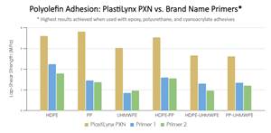
XlynX’s PlastiLynx PXN crosslinking primer enhances polymer adhesion
PFAS-free diazirine primer makes surfaces receptive to all manner of adhesives, including epoxies and polyurethanes, outperforming alternative options by 150-350%.
Read MoreIPSA acquires bonding adhesives based on MMA technology
IPS Adhesives (IPSA) introduces a line of adhesives using acrylate and MMA technology from L&L Products for the bonding of dissimilar materials such as metals and composites.
Read MoreScott Bader, Oxeco partner for high-performance bonding solution
Joint technology breaks barriers to bonding lightweight flexible solar panels to roofing structures made from aluminum, coated steel and composites.
Read MorePittsburgh engineers receive $259K DARPA award for mussel-inspired underwater adhesion
The proposed META GLUE takes inspiration from hydrogels, liquid crystal elastomers and mussels’ natural bioadhesives to develop highly architected synthetic systems.
Read MoreRead Next
Developing bonded composite repair for ships, offshore units
Bureau Veritas and industry partners issue guidelines and pave the way for certification via StrengthBond Offshore project.
Read More“Structured air” TPS safeguards composite structures
Powered by an 85% air/15% pure polyimide aerogel, Blueshift’s novel material system protects structures during transient thermal events from -200°C to beyond 2400°C for rockets, battery boxes and more.
Read MoreAll-recycled, needle-punched nonwoven CFRP slashes carbon footprint of Formula 2 seat
Dallara and Tenowo collaborate to produce a race-ready Formula 2 seat using recycled carbon fiber, reducing CO2 emissions by 97.5% compared to virgin materials.
Read More


