Variable-axial composites open path to lighter composite structures
CFRP recurve bow riser demonstrates design and manufacturing approach with potential to cut weight vs. aluminum by 50-75% while increasing strength and stiffness.
Share
Tailored fiber placement (TFP) is an automated preforming technology that uses modified CNC embroidery machines to create preforms for lightweight, load-optimized composite structures with practically zero waste. Equipped with multiple stitching heads, these industrial machines can perform 1,000 zigzag stitches per minute per head at a speed of 5 m/min.
According to licensed supplier Tajima GmbH/FilaCon Systems (Winterlingen, Germany), more than 100 TFP machines have been installed for producing composites in Europe and Asia. Parts manufactured include Airbus A350 window frames, helicopter longerons, bicycle brake levers and other sporting goods parts, as well as structural automotive components (see Tailored Fiber Placement: Besting metal in volume production).
A TFP strength is its ability to produce fiber patterns to meet practically any load path, including curvilinear shapes with radii as tight as 5 mm. Because it can deposit continuous fiber with such a high degree of freedom, TFP is described as filling a gap between additive manufacturing and automated fiber placement (AFP).
“TFP enables variable-axial composites,” says Dr. Axel Spickenheuer, head of the complex structures group in the Composites Department at Leibniz Institute of Polymer Research (IPF, Dresden, Germany), where TFP was developed. “Multiaxial composites are made of unidirectional layers, with each discrete layer having constant thickness and fiber orientation,” he explains. “In variable-axial composites, both thickness and fiber orientation may be locally adjusted to meet stiffness or bearing load requirements.” Spickenheuer’s group demonstrated computer-aided modeling and efficient manufacturing of a variable-axial composite via the rec16 recurve bow riser.
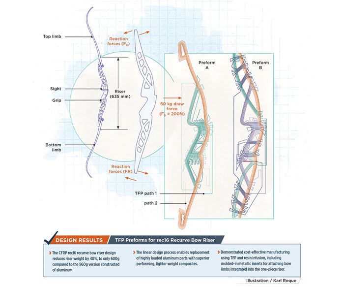
A recurve bow is identified by curved tips at either end, which increase the bow’s speed and the smoothness of its release. Widely used in target archery, it is the only style of bow permitted in the Olympics. Higher poundage recurve bows are used in field archery and bowhunting. The bow’s riser is the center structure that connects the top and bottom limbs, and where the bow grip and sight are attached (see drawing). The effort was so successful, the riser captured a 2017 JEC Innovation Award. But Spickenheuer points out, “Our objective was not to become a manufacturer of bow risers, but instead to demonstrate this design and manufacturing approach as a valid, cost-effective means of achieving next-generation composite parts.”
Five-step design process
The recurve bow was, however, an excellent choice for a demonstration. Although risers for such bows are most often made from aluminum, and weigh 950-1,400g, they also are made from wood and carbon fiber-reinforced plastic (CFRP). However, most CFRP risers, weighing in at 1,000-1,350g, aren’t any lighter than aluminum. Speckenheuer’s team at IPF knew that, with TFP, they could do better.
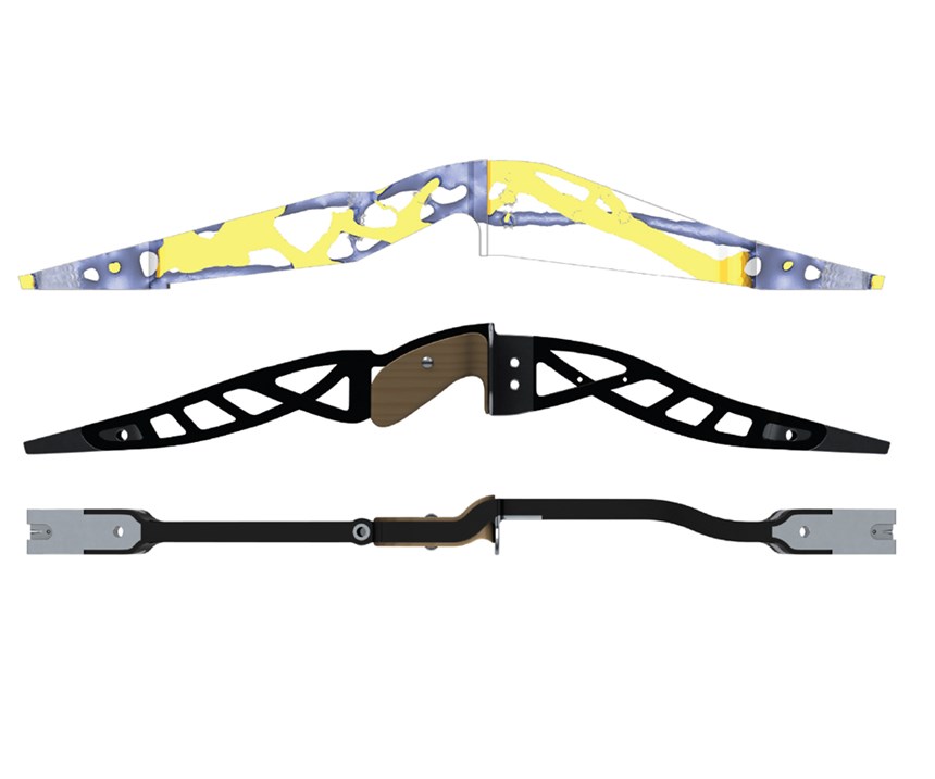
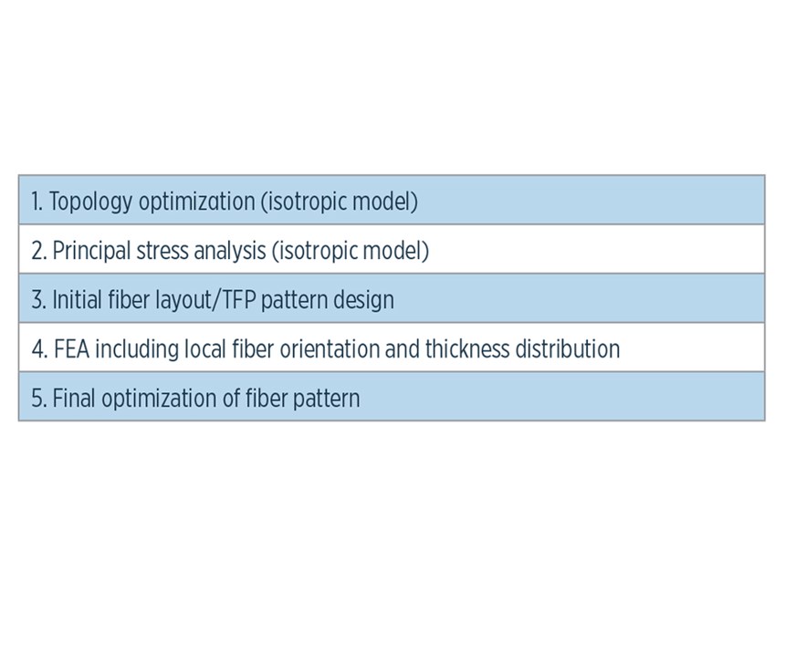
The design approach for the rec16 recurve bow riser began with identification of the structure’s load cases. A linear process was then followed, comprising five basic steps. The first step was completing topology optimization, using finite element analysis (FEA) software tools, including TOSCA (Dassault Systèmes, Vélizy-Villacoublay, France).
Topology optimization (TO) uses numerical analysis to find the best distribution of material given an optimization goal — in this case, lightest weight — and set of design constraints (for the riser, 200N lateral load, 635 mm height). Applied to any material, not just composites, it begins by taking a basic volume of isotropic material and removing from it to maximize the objective. For example, a bracket no longer comprises solid planar pieces, but instead, material is placed only along load paths, resulting in a very organic-looking structure, similar to a tree limb. Based on the TO results, students from the University of Applied Science, Faculty of Design (Dresden, Germany) worked with the IPF group to develop an initial shape (Fig. 2).
In Step 2, the TO result was developed into a 3D model, using Dassault Systèmes SolidWorks. This model was used to complete a principal stress analysis, using ANSYS finite element (FE) software (ANSYS Inc., Canonsburg, PA, US). The main load case for this FEA stress analysis was a typical recurve bow draw force of 60 kg or 200N.
In Step 3, the results of the principal stress analysis were used to draw an initial fiber pattern, using 2D CAD software.
This pattern was applied in Step 4 to derive a 3D FE model, using Advanced Optimal Path Software (AOPS) developed by IPF. AOPS features import and export functionality for several FE solvers, and can generate and export principal stress trajectory plots of an initial structural calculation to create an optimized TFP pattern.
When the TFP fiber path had been refined to consider manufacturing aspects, AOPS became an FE pre-processor, generating a 3D variable-axial composite model that would account for specific local fiber orientation as well as the local variable thickness of the intended TFP part. This enabled a design loop, where every change of the curvilinear fiber layout led to a different FE model with specific structural properties. With this tool, composites engineers can manually optimize even complex curvilinear fiber structures to achieve the overall structural objectives.
In Step 5, the basic fiber pattern of the riser’s 3D design was refined for the TFP manufacturing process by using EDOpath software (TAJIMA/FilaCon), which transforms the path data into a CNC-based stitch pattern that is readable by modern TFP machines. The final riser design called for eight carbon fiber preforms — four sets each split between preform A and preform B (see right side of drawing, p. 101) — which were stacked to achieve a symmetric laminate.
Materials and manufacturing
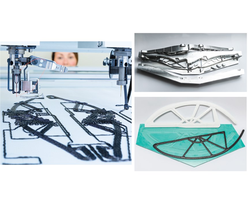
The fiber chosen to create the rec16 riser was 24K ultrahigh-modulus (UHM) carbon by Toho Tenax Europe GmbH (Wuppertal and Heinsberg, Germany) with a nominal linear density of 800 tex. It was applied and fixed with a 10-tex polyester stitching yarn onto a 108-g/m² woven glass fabric. The preforms were produced at IPF, using a TAJIMA dual-head machine (Fig. 3).
The riser was resin infused, using epoxy resin. Because the molding process did not require high pressure, but only vacuum, less costly tooling could have been used. But because the riser structure features many openings and an out-of-plane 3D shape, and requires integrated metal inserts as well as a high-quality surface finish, an unsealed but closed aluminum tool was selected, i.e., multi-part molds were matched but not designed to seal as they would be for resin injection.
The manufactured preforms were placed in the tool and infused with PoxySystems EP L + EPH L room-temperature-cure epoxy resin supplied by R&G Faserverbundwerkstoffe (Waldenbuch, Germany). No further trimming or machining was required.
Redefining designs, revolutionizing properties
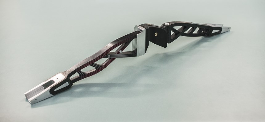
The CFRP rec16 riser design reduces weight to 600g, a 40% weight reduction, while increasing the mass-specific stiffness by 43%. “Manufacturing waste was also reduced,” notes Spickenheuer, “especially in comparison to milled aluminum risers.” Further iteration of the rec16 riser design is in process. “We did not achieve sufficient bending stiffness with the first preforms, which causes too much torsion in the upper arm,” Spickenheuer explains, “so we will increase the use of ±45° fibers.”
“TFP makes it possible to place carbon tows in any orientation to match the highly stressed regions of the part architecture,” he points out. “The results are complex curvilinear structured preforms that are able to utilize the full potential of anisotropic carbon fiber composites.”
Spickenheuer’s team has since employed a similar five-step design process to redesign and replace two aluminum attachments for the rear wing of a racecar, using variable-axial CFRP.
The original aluminum part weighed 397g. The main load case was a 750N downforce. Five TFP CFRP wing attachment designs were compared, as was a more conventional quasi-isotropic, multiaxial composite design. In numerical calculations, the best TFP variable-axial design increased mass-specific part stiffness compared to the multiaxial CFRP part by 68% and reduced weight by roughly 50%. However, compared to the original metal part, specific stiffness was increased by 236% while mass was cut by almost 75%.
The TFP CFRP part was designed as a sandwich structure to improve out-of-plane bending stiffness. This was achieved by stitching one of the two required symmetrical preforms onto a 4-mm thick layer of Lantor Composites’ (Veenendaal, The Netherlands) Cormat XM, a glass fiber fleece that contains hollow polymer microspheres with a honeycomb pattern imprinted on the surface to promote resin flow. The second preform was stitched onto a 108-g/m² woven glass fabric. Both preforms used the same UHM carbon fiber and polyester stitch yarn featured in the rec16 bow riser.
A one-sided mold, adapted for the preforms’ nonhomogeneous thickness distribution, was used to avoid mechanical coupling between in-plane and out-of-plane responses. Because only a few parts were needed, tooling cost was minimized by 3D printing a plastic master from which a silicon rubber lower mold was pulled (Fig. 3). The durable, heat-resistant material provided a self-releasing surface; no additional parting agent was required. The attachment preforms were bagged and infused with the same room-temperature epoxy resin used in the bow riser. A 10-hour cure was followed by a 10-hour postcure at 60°C. Finished parts were trimmed, holes were drilled and the parts were attached to the Elbflorace racer SophE, which won its competition in 2016.
“We have demonstrated how to combine TFP variable-axial composites with an optimization loop that couples FEA and refinement of the fiber path,” says Spickenheuer, “and proven its ability to produce extremely lightweight, high-performance composite structures.”
Related Content
Plant tour: Arris Composites, Berkeley, Calif., U.S.
The creator of Additive Molding is leveraging automation and thermoplastics to provide high-volume, high-quality, sustainable composites manufacturing services.
Read MoreMito Materials graphene amplify composite fly fishing rod performance
Functionalized graphene addition to premium-performance Evos and Evos Salt fly rods by St. Croix Fly enables faster recovery, increased torsional rigidity and improved strength-to-weight ratios.
Read MoreRepurposing wind blades as functional community art pieces
Ohio-based Canvus Inc. upcycles fiberglass wind blades, car tires and post-consumer plastics to create outdoor furniture that amplifies sustainability messages in community spaces.
Read MoreCarbon Mobile carbon fiber powers handheld gaming platform
HyRECM technology effectively stabilizes carbon fiber’s electrical and antenna properties, enabling development of next-gen electronics, such as the Snapdragon G3x Gen 2.
Read MoreRead Next
Plant tour: Daher Shap’in TechCenter and composites production plant, Saint-Aignan-de-Grandlieu, France
Co-located R&D and production advance OOA thermosets, thermoplastics, welding, recycling and digital technologies for faster processing and certification of lighter, more sustainable composites.
Read MoreDeveloping bonded composite repair for ships, offshore units
Bureau Veritas and industry partners issue guidelines and pave the way for certification via StrengthBond Offshore project.
Read MoreAll-recycled, needle-punched nonwoven CFRP slashes carbon footprint of Formula 2 seat
Dallara and Tenowo collaborate to produce a race-ready Formula 2 seat using recycled carbon fiber, reducing CO2 emissions by 97.5% compared to virgin materials.
Read More

