X-rays for NDT of composites
Nondestructive test (NDT) methods can be employed during the design, manufacture and in-field maintenance of composite components.
Nondestructive test (NDT) methods can be employed during the design, manufacture and in-field maintenance of composite components. Those most commonly used for composites can be divided into two general categories: contact and noncontact.
Ultrasonic testing (UT) is the most popular contact NDT method, used extensively to detect anomalies in typically thin laminar composites. Used in most aerospace applications to check for matrix porosity, bonding in honeycomb sandwich structure, disbonds and wall thickness in more complex parts, UT is applicable to glass and carbon fiber composites up to 50 mm thick.
Radiographic testing (RT) is a noncontact NDT method with a long history in composites. It uses short wavelength electromagnetic radiation — X-rays or gamma rays — or beams of atomic particles (e.g., neutrons). Compared to the wavelength of visible light (6,000 angstroms), the very short wavelengths of X-rays (1.0 angstrom) and gamma rays (0.0001 angstrom) enable them to penetrate materials that light cannot. Their value in NDT is based on differential absorption of the radiation; that is, different parts of a test piece will absorb different percentages of penetrating radiation due to variations in material density, thickness or composition. Unabsorbed radiation passes through the part and is captured on film or photosensor, and then shown on a fluorescent screen or monitored by various electronic radiation detectors.
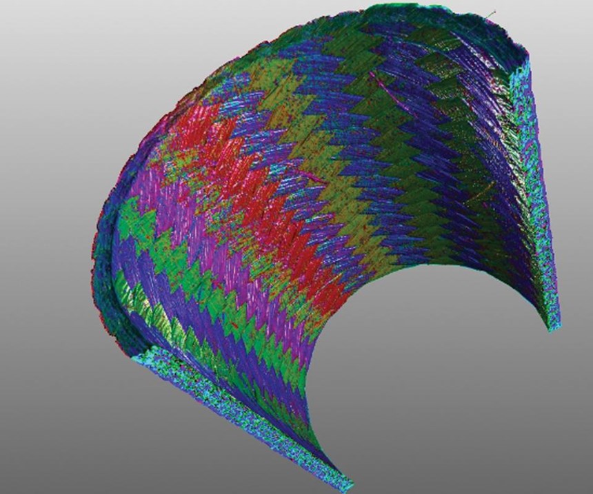
Conventional (X-ray) RT is most useful when the parts are neither too thick nor too thin. Gamma rays are better for thick parts, because they have shorter wavelengths, while low-voltage radiography may be used for thin parts (1-5 mm thickness). RT can detect voids and porosity, inclusions, trans-laminar cracks, resin-to-fiber ratio, non-uniform fiber distribution and fiber misorientation, such as fiber folds, wrinkles or weld lines. It is advantageous for larger 3D woven composites, which may be too thick for meaningful UT results. In typical RT results, one can see warp, weft and tow features and quantify their directions and positions in a part.
Although delaminations typically can be seen in conventional RT only if their orientation is not perpendicular to the X-ray beam, new techniques of computed/digital laminography are overcoming this limitation, using X-rays to scan and visualize the interiors of large, at composite components.
There are a variety of RT methods for different applications:
• Film radiography: An X-ray source placed on one side of the object is used to expose a film on the other side of the object for a fixed period. The film is then developed using chemicals.
• Computed Radiography (CR): Basically the digital replacement of traditional film. Instead of using chemicals to develop a film, a laser scanner digitizes the image.
• Digital Radioscopy (DR): This form of X-ray imaging uses digital imaging detectors connected to a computer, which enables the user to look at images in real time.
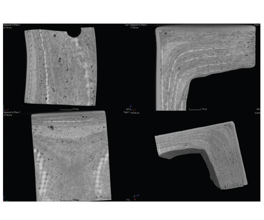
• Computed Tomography (CT): This method requires the object (or the source and detector) to rotate up to 360°. Images are taken during the rotation, and then software reconstructs virtual slices of the object. It is an excellent technique for 3D visualization of a part’s interior features.
• Digital Laminography (DL): For large composite parts, this method typically does not require the part to be moved. The relative movement of the detector and the source can be on a circular trajectory or a vertical and horizontal path. The result, after reconstruction, is a set of images in different planes across the part.
There are also new methods being adapted to composites. Back-scatter X-ray, typically used in full-body airport security scans, detects the radiation reflected from the target instead of what passes through, enabling inspection where access is limited to a single side of the component. Neutron radiography has been used to detect moisture ingress, honeycomb cell corrosion and adhesive/composite hydration in aircraft flight-control surfaces. It provides images similar to conventional RT but offers higher resolution, detecting elements such as hydrogen and carbon. Thus, organic materials and water are clearly visible in neutron radiographs, which often provide complementary information to normal X-ray inspection.
Perhaps the most beneficial improvement in RT in the past decade has been the accelerated development in X-ray detectors and computer processing of data and images. Data now can be captured at very high resolutions. A resolution of one millionth of a meter is possible in micro-focused CT scanning, for example. Data also can be processed into 3D images as well as numerically analyzed. Further, a variety of quantitative analyses are possible:
• Defect analysis: CT scanning can detect and quantify percentage porosity in a composite part, measuring void diameter and volume, as well as distance from the edge of the part. It also can be used to walk through the layers of a part from any direction, enabling visualization of how porosity, weave structures and fiber orientation change from top-to-bottom and side-to-side.
• Resin/Fiber Analysis: CT can detect different densities of material within a part, enabling the removal of resin digitally to analyze fiber distribution in the as-made part, including calculation of resin/fiber content and measurement against set thresholds to flag where the part is not hitting spec. Fiber orientation and fiber length distribution also can be analyzed and flagged against spec.
• Wall thickness: The thickness of every wall throughout an entire part can be measured — regardless of the number of cavities, stringers, complex ribs/stiffeners, etc., returning a visual plot similar to finite element analysis, with colored indicators showing where wall thickness is compromised by porosity.
• Dimensional check: CT part scan is compared to its CAD file (CATIA, Solidworks, NEX, etc.) to check actual against design dimensions. While only 6-12 points are typically recorded with a coordinate measuring machine (CMM), CT measures thousands of points, including contours and interiors. When the measurement template is created, every part afterward is analyzed in seconds, not hours. Output includes exact deviation at every location and comparison of dimensions from part to part to check for manufacturing consistency, how parts have changed over production time or due to design or process iterations, etc.
• Data for process simulations: CT analysis can be used to create polygon files, STLS or point clouds, similar to measurements from vision-based technologies, except that information is provided for the part’s interior as well as its exterior. For example, files including porosity, void and fiber orientation can be imported into Moldflow injection and compression molding software (Autodesk Inc./Moldflow Corp., Waltham, MA, US) to run simulations using actual part information vs. theoretical parts.
• Damage mechanism and failure analysis: CT also is a powerful tool in structural and failure analysis, enabling the identification of failure modes in even the most complex structures, without destructive testing that might compromise data.
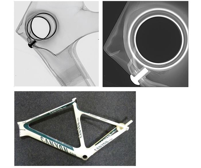
Who is using these technologies? The aerospace industry uses RT widely for wing, fuselage and engine components. The automotive industry has used RT and CT since the 1990s, and sporting goods companies have adopted it as well. Professional cycling teams use X-ray inspection to ensure the performance of their composite equipment, and manufacturers of composite baseball bats and tennis rackets use it to maintain quality control. More recently, increased failures in these structures have illustrated the value of RT in determining failure causes and remediation required.
As composites applications grow and the industry becomes more efficient in manufacture and design, so will the need for inspection and the opportunity for the latest developments in X-ray technology.
To learn more, access YXLON’s recent webinar, hosted by CompositesWorld | info.yxlon.com/industrial-computed-tomography-composites-webinar
Related Content
The basics of composite drawing interpretation
Knowing the fundamentals for reading drawings — including master ply tables, ply definition diagrams and more — lays a foundation for proper composite design evaluation.
Read MoreATLAM combines composite tape laying, large-scale thermoplastic 3D printing in one printhead
CEAD, GKN Aerospace Deutschland and TU Munich enable additive manufacturing of large composite tools and parts with low CTE and high mechanical properties.
Read MorePlant tour: BeSpline/Addcomp, Sherbrooke, QC, Canada
Composites automation specialist increases access to next-gen technologies, including novel AFP systems and unique 3D parts using adaptive molds.
Read More3D-printed CFRP tools for serial production of composite landing flaps
GKN Aerospace Munich and CEAD develop printed tooling with short and continuous fiber that reduces cost and increases sustainability for composites production.
Read MoreRead Next
All-recycled, needle-punched nonwoven CFRP slashes carbon footprint of Formula 2 seat
Dallara and Tenowo collaborate to produce a race-ready Formula 2 seat using recycled carbon fiber, reducing CO2 emissions by 97.5% compared to virgin materials.
Read MoreVIDEO: High-volume processing for fiberglass components
Cannon Ergos, a company specializing in high-ton presses and equipment for composites fabrication and plastics processing, displayed automotive and industrial components at CAMX 2024.
Read More“Structured air” TPS safeguards composite structures
Powered by an 85% air/15% pure polyimide aerogel, Blueshift’s novel material system protects structures during transient thermal events from -200°C to beyond 2400°C for rockets, battery boxes and more.
Read More
