ZAero project update
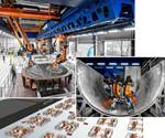
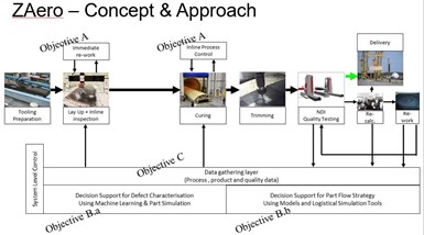
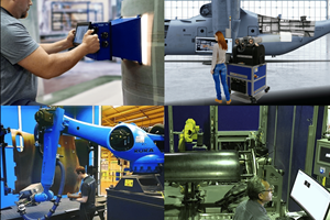
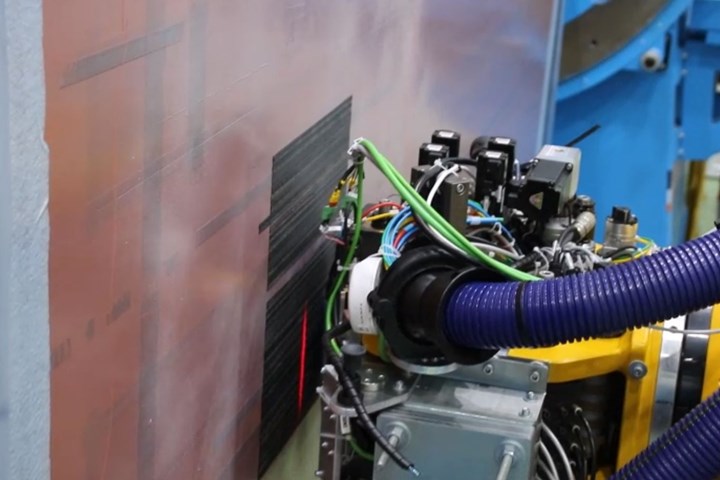
The 2019 final review demonstrated integration of an automated CFRP process chain: AFP inline inspection and rework, cure and resin flow sensors, part performance prediction and a decision support tool for line operators.
Source | Profactor
This is an online sidebar for the July 2020 article, “Composites 4.0: Digital transformation, adaptive production, new paradigms”.
Started in 2016, the ZAero project aimed to improve the production process for large carbon fiber-reinforced polymer (CFRP) parts, such as wingskins for commercial aircraft (see “Zero-defect manufacturing of composite parts”). The ZAero project won the 2019 JEC Innovation Award for Aerospace Process.
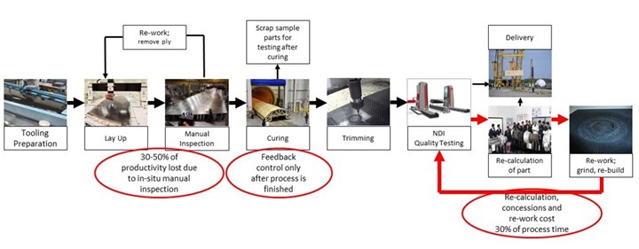
Project partners and goals were introduced in a 2018 blog. The main focus was to reduce CFRP part defects by integrating inspection during automated fiber placement (AFP) of dry materials along with process monitoring during resin infusion. Collected process and defect data were then used with FEA to predict part performance, with results then input into a decision support tool to simulate part flow and optimize a rework strategy. Goals included a 15% higher production rate, 15-20% lower production cost and 50% less waste due to process control and earlier rework.
Sources for this blog include:
- “ZAero- Zero defects in the manufacture of composite material parts in the aerospace industry,” by A.R. Rodriguez1, J. Cuenca1, R. Ruiz1, A. Calero1. 1FIDAMC (Getafe, Spain). Materiales Compuestos, Vol. 2, No. 2 (2018) pp. 128-131.
- ZAero project poster
- “Using business analytics for decision support in zero defect manufacturing of composite parts in the aerospace industry,” by Helmut Zörrer, Robert Steringer, Sebastain Zambal, Christian Eitzinger. Profactor (Steyr, Austria). IFAC Papers Online, Vol. 52, Issue 13 (2019) pp. 1461-1466.
- “Deliverable D5.3 – Demonstration #3 and evaluation report” by project coordinator Christian Eitzinger (Profactor) with contributions by Airbus Group Innovations (AGI), Danobat, Dassault Systemes, FIDAMC, IDEKO, InFactory Solutions and MTorres.
- ZAero Review Meeting Sep 2019:
WP2 In-process quality control by Sebastian Zambal (Profactor), Christopher Buchmann (AGI/InFactory Solutions) and Alberto Mendikute (IDEKO)
WP3 Defect handling and decision support by Michael Clarke (Dassault Systèmes) and Miguel Sanchez (MTorres)
WP4 Part flow decision support by Helmut Zörrer (Profactor).
Materials
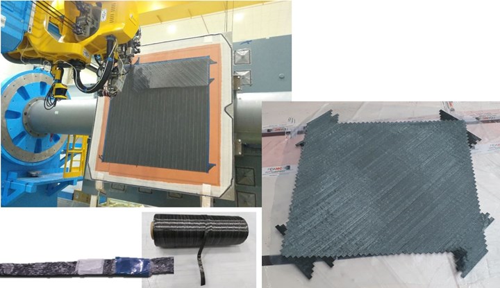
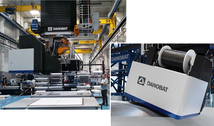
ZAero used two different dry fiber placement technologies: Danobat’s (Elgoibar, Spain) automated dry material placement (ADMP) and MTorres’ (Torres de Elorz, Navarra, Spain) dry AFP
(DFP).
ADMP layup used a 600-millimeter-wide dry carbon fiber multiaxial noncrimp fabric (NCF) while DFP used a 12.7-millimeter-wide unidirectional (UD) dry tape produced by MTorres. This new dry fiber tape technology was reviewed at CW’s CarbonFiber 2019 conference by Iñigo Idareta, MTorres head of special projects.
Work with ADMP was carried out at Danobat facilities while DFP demonstrators and inspection evaluations were completed at FIDAMC (Getafe, Spain), a key partner in the ZAero project.
Demonstrators
The first demonstration in 2017 tested layup monitoring on a flat CFRP skin panel. Demonstrator 2 was a 1700-millimeter by 1700-millimeter double-curved panel with a ply build-up in one corner, used to test layup inspection and cure monitoring in 2018. Layup monitoring focus shifted from mainly ADMP for the first two demonstrators to DFP for the third and final demonstration.
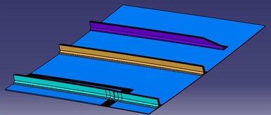
CAD model for ZAero project Demonstrator 3.
Source | Deliverable D5.3 – Demonstration #3 and evaluation report by Eitzinger (Profactor)
The final project review at FIDAMC included a 1500-millimeter by 1500-millimeter double-curved demonstrator based on a section of the Airbus A350 lower wingskin with three integrated T stringers. One of the stringers contained a stagger (taper) and another contained a run-out (region at the termination to transition the load into the skin). The panel also retained the corner reinforcement from Demonstrator 2.
Demonstrator 3 was created using DFP with a multi-tow head applying eight 12.7-millimeter-wide tows. A dedicated laser on the lay-up head heated the material above 170°C to achieve sufficient tack and bond the plies.
Layup sensors and defect detection
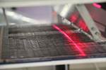
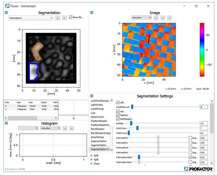
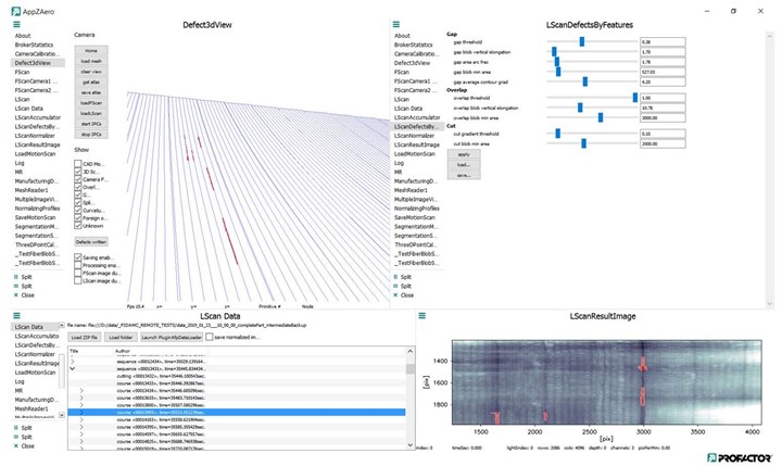
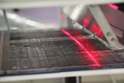
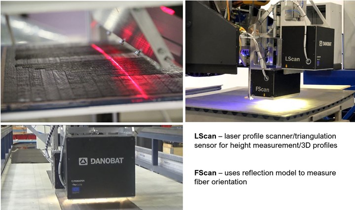
“The ZAero project has developed and demonstrated inline sensor systems for both ADMP and prepreg AFP/DFP processes,” says Dr. Christian Eitzinger, head of machine vision for Profactor (Steyr, Austria) and project coordinator. Two different non-contact sensors were developed for inline defect detection during layup. A photometric stereo sensor (FScan) with five cameras uses a reflection model of carbon fiber to measure fiber orientation. It is used only with ADMP. A laser profilometer/triangulation sensor (LScan) with three cameras is used to acquire 3D profiles during both ADMP and DFP.
Source | Profactor, “Using business analytics ...” by Zörrer (Profactor) and ZAero poster.
The FScan sensor was developed with Danobat. “We needed their input regarding the quality criteria necessary for their ADMP machine and also to link tightly its motion control with the data acquisition of the sensor,” explains Eitzinger. “The LScan sensor is based on the same type of technology as what InFactory qualified with MTorres [see 2018 blog], but with some modifications made during the ZAero project. It can also detect other standard AFP defects such as overlaps, FOD (foreign object debris), fuzzballs and twisted tows, as well as early cut and late cut of each single tow to determine if the designed cuts are indeed in the right place.”
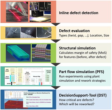
The large data amount from both sensors is aggregated by edge computing and combined to identify features, along with their size and location. The overall inspection result is written to the manufacturing database (MDB), which also contains the CAD-model for the part. In a next process step, a structural simulation (finite element simulation) is performed for all features found on a ply. The MDB and structural simulation together can thus serve as support for a digital twin of the ply.
Defect evaluation and rework
The large amount of data from these sensors is aggregated by edge computing and combined to identify features in each ply along with their size and location. The overall inspection result is written to the manufacturing database (MDB), which also contains the CAD model for the part.
“We have built this database using Dassault Systemes’ 3D Experience for the CATIA environment,” says Eitzinger. “It allows us to calculate the effects of various defects on the part’s performance, for example, how much the margin of safety is reduced for a given size, shape and type of defect.”
Next, a finite element structural simulation is performed for all features found on a ply. The MDB and structural simulation together can thus serve as support for a digital twin of the ply. This then provides information for the machine operator to decide what defects can be left and what must be reworked.
“We have also implemented with MTorres the ability to rework,” Eitzinger points out. “For example, a missing tow can now be replaced automatically by placing an additional tow in the precise location where it is missing.”
Can all of these defects be corrected automatically? “Some will require that the machine be stopped, for example, to remove fuzzballs or a twisted tow,” he explains. “To proceed, however, requires some machine intelligence. You must tell the machine that tow #27 needs to be replaced and the machine must learn to replace only that single tow, not the entire layer, before proceeding to the next layer.”
Infusion sensors
Once layup and necessary rework during AFP was completed, the dry fiber laminate was prepared for resin infusion with RTM6 epoxy (Hexcel, Stamford, Conn. U.S.). Different sensors were integrated into the vacuum bagged infusion setup to monitor resin temperature, flow front and degree of cure. Using a typical RTM6 cure cycle, resin was heated in the reservoir to 90°C and degassed at vacuum for 30 minutes. Once the part tooling was heated to 120°C, an injection unit was used to infuse the resin into the dry laminates, followed by cure at 180°C for 90 minutes.
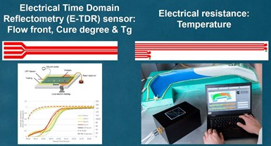
Resin flow front and degree of cure monitoring uses sensors based on electrical time-domain reflectometry (see “Sensors for monitoring resin infusion flow front and cure”).
For temperature monitoring, a novel, thin-film foil-based array provided measurement for 14 individual sensor locations. Each sensor stripe was folded with one part inserted below the laminate, on top of the metal tooling, and two parts above the stringer laminates. Through various tests and demonstrations, these sensor arrays were validated to provide accurate, online monitoring of temperature distributions and small temperature deviations.
“We now have sensors that measure three different process parameters: temperature, state of cure and resin flow front during infusion,” says Eitzinger. “We have tested and integrated these with CATIA 3D Experience and shown that the data can be reliably acquired and added to the part’s database.”
Decision support tool
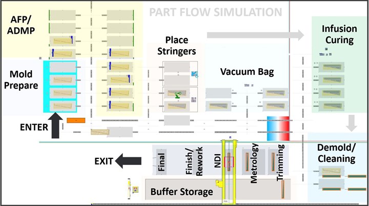
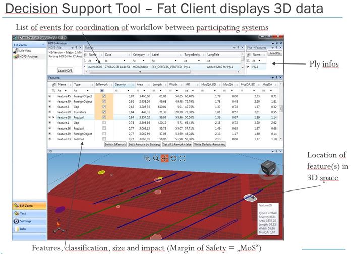
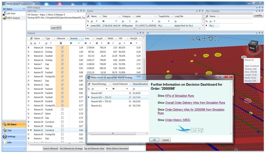
To optimize rework strategies, the ZAero project developed a decision support tool (DST) that reads manufacturing database defects and structural simulation results and then visualizes that data for two distinct user roles: machine operator and line manager. The DST uses a part flow simulation (PFS) to run experiments for different rework strategies.
The machine operator must decide which defects have to be reworked and perform the rework before another ply can be placed. He/she is interested in the estimated delivery for the current order.
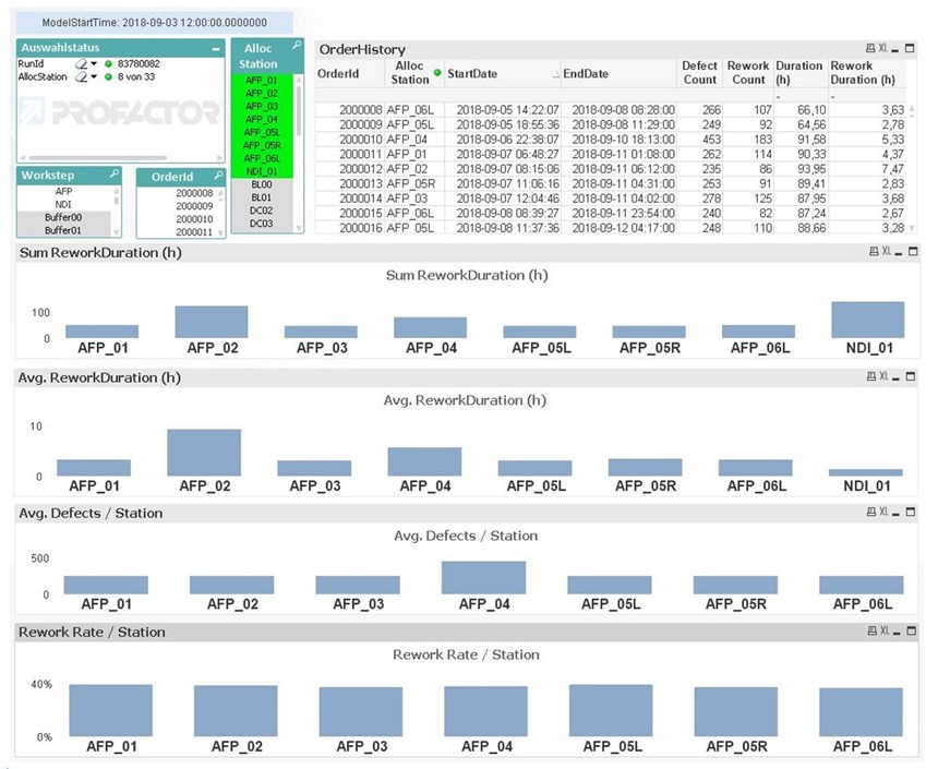
The line manager is responsible for delivering all orders on time and ensuring that resources are available to match the demand. He/she can run different PFS experiments — for example, with more or less DFP/ADMP stations — and thus evaluate different options to ensure order fulfillment.
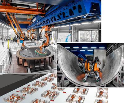
The ZAero part flow simulation (PFS) model was built using Siemens PLM (Plano, Tex., U.S.) Tecnomatix Plant Simulation software and includes all machines and processes in the CFRP wingskin production chain. Source | ZAero Review Meeting Sep 2019, WP4 Part Flow Decision Support, Helmut Zörrer, Profactor.
The DST combines a specialized fat client software application that visualizes the 3D data from inline defect detection and enables the execution of rework decisions, with web-based business analytics dashboards that support the decision-making task. The dashboards display data from a manufacturing execution system (MES) or production data acquisition (PDA) system as well as results from PFS experiments using different rework strategies. These interactive dashboards use the business intelligence product QlikView that also operates as a web server. Users can easily extend the dashboards to display additional data of value from other sources on the shop floor.
Decision Support Tool
Next Steps?
“We want to create a full production line, from the beginning of layup through infusion to cure and then incorporate final NDT,” says Eitzinger. “We would like to equip this line with sensors and the full ZAero control system, and then partner with a Tier 1 to demonstrate.” In the meantime, Profactor is commercializing modular sensors for fiber orientation and defects during automated layup. InFactory Solutions is also offering its AFP and resin infusion sensors and Danobat and MTorres are now selling their equipment with integrated inline inspection.
What was the largest challenge? “Putting all of the new devices and software together to make one system was a challenge, requiring a smooth transfer of data and in a usable format,” notes Eitzinger. “So, integration was one of the more challenging tasks.” He believes that ZAero’s development of inline AFP monitoring and its demonstration, on real equipment, that this data can be used to improve production efficiency will have a significant impact. “Not only will this increase production so that more composite products can be made reliably with reduced cost,” says Eitzinger, “but the sensors will provide the further opportunities of big data, which opens the door to the next steps in smart composites 4.0 manufacturing.”
Related Content
Nondestructive inspection methods available to composites manufacturers
An overview of composite laminate inspection techniques ranging from manual testing methods to more advanced, noncontact options.
Read MoreLaser NDT, DIC systems demonstrate optimized noncontact composites inspection
CAMX 2024: Dantec Dynamics is presenting three of its laser shearography NDT and DIC devices, geared toward reliable measurement results.
Read MoreInfrared NDT well-suited to demanding in-service, manufacturing and research applications
CAMX 2023: High-precision, cost-effective thermographic NDT technologies offered by Thermal Wave Imaging addresses real-world inspection challenges.
Read MoreNDT inspection services, automated systems serve aerospace needs
CAMX 2023: Arcadia Aerospace Industries demonstrates its commitment to navigating the rapidly changing aerospace manufacturing landscape with robotic-based machines and motion control systems, certified facilities for NDT services and conducted training and recruitment.
Read MoreRead Next
Composites 4.0: Digital transformation, adaptive production, new paradigms
An evolving landscape of automation, sensors and AI software is not an end, but a means to achieve the cost, quality, efficiency and agility required for future manufacturing.
Read MoreZero-defect manufacturing of composite parts
ZAero project aims for 30-50% boost in productivity via inline AFP inspection, simulated part performance and decision support tools.
Read MoreAll-recycled, needle-punched nonwoven CFRP slashes carbon footprint of Formula 2 seat
Dallara and Tenowo collaborate to produce a race-ready Formula 2 seat using recycled carbon fiber, reducing CO2 emissions by 97.5% compared to virgin materials.
Read More

