Nondestructive inspection methods available to composites manufacturers
An overview of composite laminate inspection techniques ranging from manual testing methods to more advanced, noncontact options.
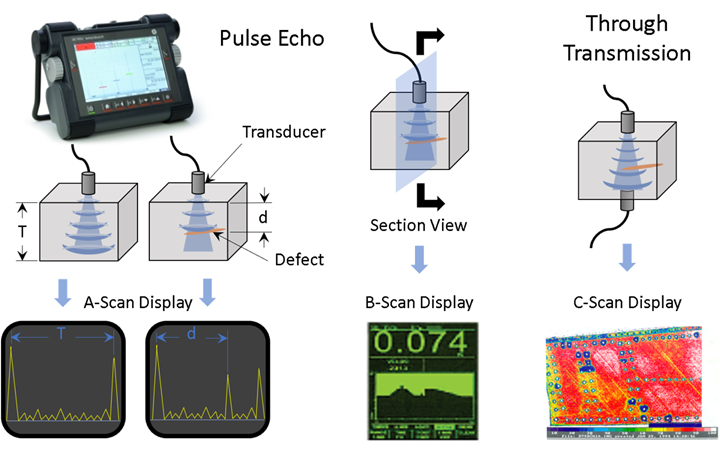
Figure 1. Ultrasonic testing using pulse echo and through-transmission methods. Pulse echo (left and center) uses a transducer that sends and receives ultrasound energy, producing both A- and B-scan displays which depict the measurable depth of the defect. Through transmission (right) uses a transmitter on one side and a receiver on the other to send ultrasound energy through the part and provides a color map of the percentage of energy received (dark purple areas are ~10%, yellow is ~70% and red is ~90%). Photo credit: Abaris Training Resources Inc.
Nondestructive inspection (NDI) is standard practice in industry and is fundamental to any manufacturing quality assurance (QA) program. There are a wide variety of methods to choose from, and sometimes more than one method may need to be employed to fully understand the type, size, location and depth of flaws and defects found in composite laminates. The goal of NDI is to detect and evaluate anomalies in a part so that QA can record them and either accept or reject the part. There are many NDI methods and techniques that can be deployed using equipment designed to meet these needs.
Laminated composites are susceptible to flaws and defects that can be introduced during layup and processing. For example, inclusions or foreign object debris (FOD) such as small pieces of prepreg backing film, release film, remnants of gloves and X-Acto blades, to name a few, are sometimes found between plies in a laminate that has been cured.
Non-FOD defects such as porosity, voids and disbonds are also commonplace in manufacturing and are generally related to materials, processes and workmanship. Because these types of flaws are prevalent, the acceptable limits of size, quantity and location of defects are (and should be) defined ahead of time by engineering (either in a specification or on the drawing) so that QA can interpret from NDI what is permissible and what is not. The more complex the configuration, or the less compacted the laminate, the more likely that defects will be found. This is why it is so important that NDI technicians and QA inspectors have a good level of understanding of composite materials and processes, as well as knowledge of the specific design. Well-trained composites inspectors know where to look and what to look for — something metallic inspectors might not do intuitively.
Visible inspection is often overlooked as an NDI method, though it is the first method employed by any technician. Viewing a composite laminate at a shallow angle under light can aid in finding obvious defects such as scratches, wrinkles, bridging, surface porosity, disbonded skins, delaminated plies, heat damage, visible impact damage and sometimes barely visible impact damage. Tap testing, another test method, is an art. The technician lightly taps the surface with a tap hammer, coin or other designated tool to listen and feel for a response from the laminate. A digital tap hammer works to measure that tap response and display the time the laminate takes to respond in milliseconds. The shorter the response time, the less the structure absorbs the impact, denoting a solid structure. When a defect is found, the response time is longer, resulting in a higher number on the display. Tap testing is useful in detecting near surface defects in thin laminates, <0.12-inch (3.05 millimeters) thick and for skin-to-core disbonds in sandwich structures.
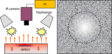
Figure 2. Pulsed thermography. Light pulse energy (heat) is directed at the surface and the IR camera detects and measures thermal conduction into the laminate (left). The image is displayed on the screen for evaluation (right). Photo credit: Thermal Wave Imaging Inc.
Ultrasonic testing (UT) is the workhorse of the composites industry and is the most widely used NDI method today. UT works by sending high-frequency (0.5-25 megahertz) energy waves into or through a laminate, capturing and quantifying the amplitude and time of flight of these wave forms. There are two primary methods in use: pulse echo which measures reflected waves by sending and receiving a pulse of sound with the same probe, and through transmission which measures transmitted waves through the laminate thickness — requiring a transmitter probe on one side and a receiver probe on the other to send and receive the sound energy. Typically, this information is converted through software to a digital screen in the form of either an A-, B- or C-scan display (Fig. 1). A matrix array or phased array probe with multiple elements can be used to provide an enhanced 2D display and/or to interpret and display data as a 3D image. These methods are often automated for rapid inspection in a production environment. UT is useful in detecting many of the above listed defects and flaws in a structure. UT requires contact with the part using water or glycerin couplant.
Thermography (thermal imaging) is the process of converting infrared (IR) radiation into visible images, presenting very small temperature gradients on a display through gray tones or color. Pulsed IR thermography works by introducing a small amount of IR energy (heat) to the structure with a pulse of light. An IR camera then captures and records the resulting heat conduction into the laminate. Specialized software helps to interpret the image and displays it on a monitor for the inspector to view (Fig. 2). This method is quick and easy and is useful in detecting porosity, disbonds, delamination and near-surface inclusions.
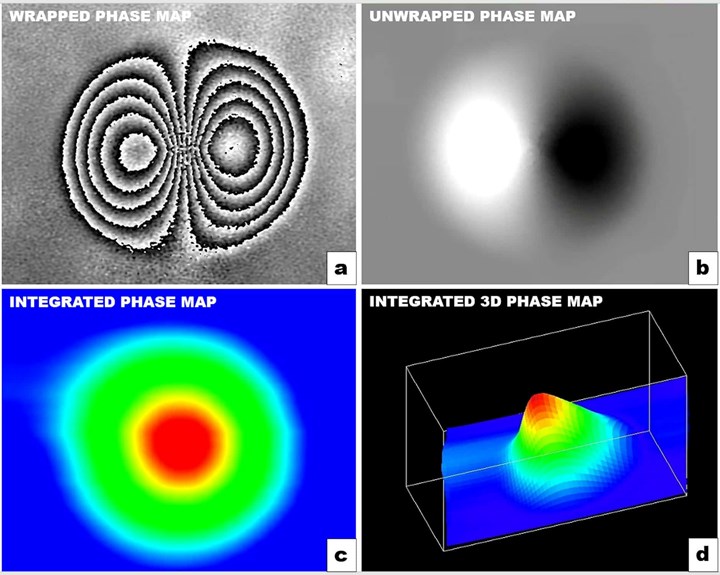
Figure 3. Laser shearography. Wrapped phase map (A), unwrapped phase map (B), integrated phase map (C) and integrated 3D phase map images of a surface defect in a composite panel. Photo credit: Laser Technology Inc.
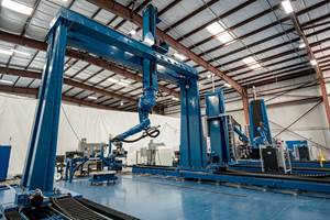
Laser shearography is a noncontact optical NDI technique that uses an image shearing interferometer to detect and measure out-of-plane deformation in a part. The part is first measured in the unloaded condition and then again under applied load — heat, mechanical vibration, acoustic vibration, pressure, vacuum, electric fields, magnetic fields, microwave or mechanical — which makes the defect visible to the video camera in order to capture an iso-strain fringe pattern on the laminate surface where subsurface defects exist. Computer software extrapolates a wrapped phase map image and creates an unwrapped phase map that is converted to an integrated visible image for display and evaluation (Fig. 3). Portable systems are used for localized inspections of isolated areas or for repairs. Production systems are designed for larger area part inspections (Fig. 4). It should be noted that LS can quickly show where a defect is located but further interrogation with UT would be required to identify the depth.
Figure 4. Laser shearography equipment. Portable unit for localized inspection (left), tripod mounted system for larger areas (middle) and gantry-mounted system for production (right). Photo credit: Laser Technology Inc.
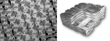
Figure 5. Computed tomography (CT) scan images. A slice of the laminate enables inspection to see the porosity at that ply layer (left). A larger section is taken and sliced to view multiple layers (right). Note how clearly you can see the fibers, resin, and void spaces in the laminate using CT. Photo credit: National Testing Systems (NTS)
Radiographic testing methods such as computed radiography use short-wavelength electromagnetic radiation such as X-rays or gamma rays that pass through a part to a photosensor (detector) which is interpreted by a digital image processor and displayed on a screen. There are limitations to what can be detected if the X-ray is taken perpendicular to the surface. For example, kissing disbonds and delaminations may not show up, but standing water in a sandwich panel will. Computed tomography (CT) is a 360° rotation X-ray of the part, or the source and detector are rotated around the part. This provides images that can be viewed as sections of the part or constructed into models of the area of interest. With a CT scan, you can clearly see all internal defects as well as the fibers, resin and voids (Fig. 5). Digital laminography is suitable for large area inspection where the part is fixtured and the source and detector either rotate around the part or move up and down along the length. (For more information, read “X-rays for NDT of composites.”)
At the end of the day, no one NDI method can do it all. Nevertheless, it is important for QA inspectors, technicians and engineers to understand the different methods and techniques available to them in their own environment. I encourage you to use what is available to you in your facility, and put this knowledge to work.
Related Content
Innovation in ultrasonic inspection and nondestructive testing
With increasingly complex structural components working their way into aerospace programs, the need for versatility in inspection and testing capabilities is growing.
Read MoreXnovo Technology, Exciscope introduce X-ray tensor tomography technique
Through a strategic partnership, the companies introduce the FiberScanner3D module, dedicated to bringing more rapid, reliable and robust fiber structure characterization methods to lab settings.
Read MorePhotothermal tomography system enhances composites NDT
JEC World 2024: Austria-based voidsy GmbH introduces the 3D V-ROX system, facilitating fast, contactless and nondestructive inspection with added efficiency and safety.
Read MoreAutomated robotic NDT enhances capabilities for composites
Kineco Kaman Composites India uses a bespoke Fill Accubot ultrasonic testing system to boost inspection efficiency and productivity.
Read MoreRead Next
Applying CT scan data analysis and visualization to composites
Imaging and analysis via computed tomography (CT) has potential for certifiable safety and business sustainability and could be key for interior inspections of composite parts. Part 1 of a two-part series.
Read MoreRobotic computed tomography – removing NDT barriers for composites
Radalytica uses collaborative robots, ultra-sensitive X-ray photon detectors and the ability to combine CT with ultrasound, surface profiling and other inspection methods to optimize composites part quality, production and reduce cost.
Read MoreHow ultrasonic testing can find flaws in composite materials
As composite applications expand, so does the demand for more capable inspection systems. Ultrasound has proven to be effective when it comes to in-depth, sophisticated testing.
Read More

