Airbus A350 Update: BRaF & FPP
EADS Innovation Works pursues qualification of Braided Frames for the A350-1000 fuselage and develops Fiber Patch Preforming for complex local reinforcements.
The Airbus A350-1000 is the Toulouse, France-based aircraft OEM’s newest and biggest A350 XWB jetliner. Its fuselage is the same diameter as other jets in the family, but it will be 7m/23 ft longer than the near-production-ready A350-900. More powerful but heavier engines will enable the 1000 variant to surpass the 900’s range by 600 km/373 miles and increase its payload by 40 metric tonnes (88,185 lb). However, the aircraft’s empty weight will go up by 2.4 metric tonnes (5,291 lb), and the plane’s cost will be $9 million (USD) more than the 900.
Airbus is pursuing weight and cost reduction efforts. One program is aimed at automating production and optimizing the weight and performance of the 1000’s carbon fiber-reinforced polymer (CFRP) fuselage frames.
The frames are the ring-like ribs that encircle the inside diameter of the fuselage, which, along with the longitudinal stringers, form the aircraft’s skeleton. Eleven additional frames will be required for the 1000’s longer fuselage, five aft of the wing and six forward. Producing identical frames is simple and cheap, but it typically does not allow for each frame to be designed to meet specific mechanical requirements based on its location in the structure. Because of this, many frames are overdesigned and, therefore, add unnecessary weight. To avoid this scenario, Airbus elected to tailor each barrel section of the fuselage (see “A350 XWB Update ...." under "Editor's Picks," at right), including its frames, to the loads each will carry. The challenge was to find a way to produce individually tailored CFRP composite frames in a serial-production environment and do so cost-effectively.
Airbus and parent company European Aeronautic Defence & Space Co. (EADS, Amsterdam, The Netherlands) had developed this process for A350-900 frames using prepreg. But for the 1000 there was an opportunity for improvement. “We knew there were areas where we could reduce the weight further,” says Matthew Beaumont, head of operations, Composite Technologies, at EADS Innovation Works (EADS IW, Ottobrunn, Germany). “Thus, instead of waiting for the next platform, perhaps 5 to 10 years away, we saw the opportunity for quick wins in weight savings and manufacturing process robustness within two to three years with the A350-1000.” He presents an image of the A350-900 as the first-generation composite fuselage and the A350-1000 as generation 1.5.
Braided CFRP frames
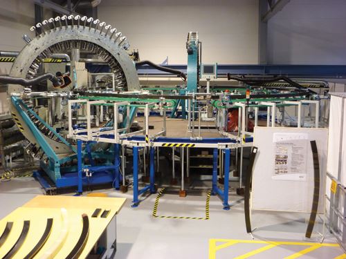
To escape the limitations of prepreg, Beaumont’s EADS IW team has worked for 10 years with Airbus and SGL Kumpers GmbH & Co. KG (Rheine, Germany) to develop a quasi-endless process for making uniaxial braided preforms from dry carbon fiber using a highly automated circular machine that is sized to the aircraft’s fuselage diameter. The preforms are then resin infused, cured and finished via computer-controlled machining and EADS-patented processes.
“It’s low risk and highly automated,” claims Beaumont, but for Airbus, he says, it’s a completely new process. “This is a big change, going from prepreg laid by automated placement machines to dry fiber braided preforms that are resin infused.” It is a new step for EADS IW, too, beyond research to real component development. And, Beaumont admits, it is a job not yet finished. “We still have a lot of work to do in order to prove out the process and product to Airbus’ satisfaction.”
A prototype Braided Frames (BRaF) production line has been in use since 2008, originally installed in Airbus’ Composites Technology Center (CTC) in Stade, Germany. It has since been moved to the larger CFK Nord research center, also in Stade.
Uniaxial braiding reduces waviness
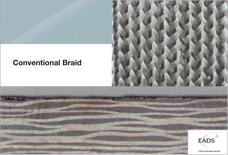
The BRaF automated braiding production line was based, initially, on an existing SGL Kümpers unit. Although it was capable of higher volume and lower production cost, it produced a product that exhibited poor mechanical properties due to fiber waviness inherent in conventional braiding. Further, the team observed that fibers were often damaged or weakened by shear forces exerted upon them during conventional braiding, or as a result of the friction at crossover points. EADS IW knew this friction could be reduced by using a machine with two braiding rings, but the fiber waviness problem would remain. Given that, EADS IW began work on its patented uniaxial braiding process.
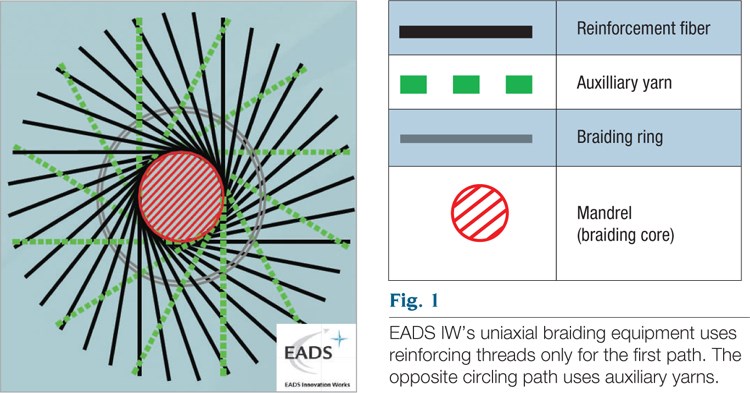
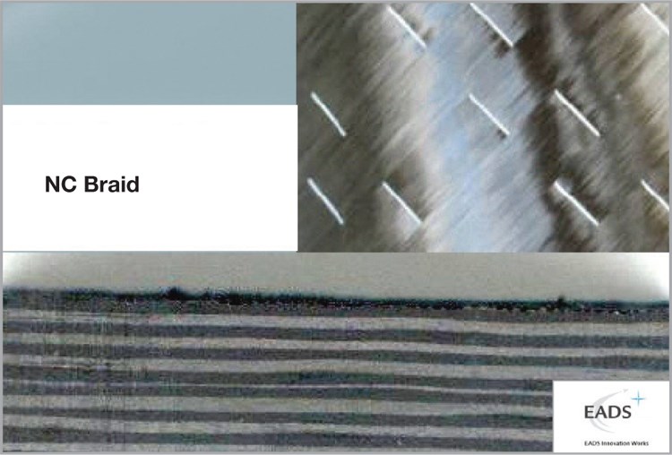
The new process, according to U.S. patent 2007/0193439 A1, resolves fiber wrinkling via two developments. First, instead of the conventional setup in which all bobbins are fitted with reinforcing fibers, EADS IW uses bobbins with reinforcing threads only for the first path and uses bobbins with auxiliary yarns (called “supporting threads” in the patent) for the opposite circular path (see Fig. 1, at right). Second, at least some, if not all, of the auxiliary yarns/supporting threads are thermoplastic fibers, which are heated to melt and then cooled to resolidify, resulting in good sliding characteristics so that friction between the crossed braiding threads is reduced, as is fiber damage. The thermoplastic threads also hold the reinforcing fibers in position after they are laid on the braiding core (mandrel). The patent explains: “The elastic thermoplastic threads are placed so snugly between the reinforcing threads that the latter come to be situated in parallel virtually without any space in-between and are therefore deposited almost without any waves” (see Fig. 2, at right). Thus, the compressive strength of the carbon fibers is improved significantly, as are the overall mechanical properties of the finished profile or frame.
To demonstrate BRaF, the team used HTS40 F13 12K 800tex (Toho Tenax Europe GmbH, Wuppertal Germany) as the reinforcement fiber and fusible polyamide K85 Grilon fiber made by EMS-GRILTECH (Domat/Ems, Switzerland) for the auxiliary yarns. All layers featured an areal weight of 260g/m2 (7.7 oz/yd2). A demonstrator stacking sequence featured 12 layers that were built up around an aluminum mandrel with a square cross-section. These layers were applied at +30° or -30°, followed by application of the same reinforcement fibers either by winding 90° layers or interleaving unidirectional (UD) dry fiber tape as 0° flange layers.
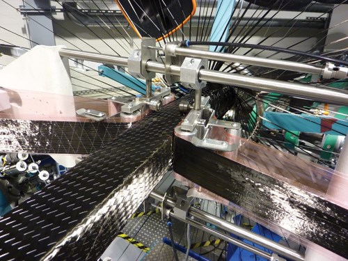
“Realistic fiber angles for normal braiding machines span ±10° to ±75°,” Beaumont explains. “Thus, it is key that BRaF includes the 0° and 90° capabilities.” The 0° unidirectional dry fiber tape is layed between the braided layers along the left and right side of the square mandrel. When the square preform is cut in half horizontally, this tape is aligned with the flanges of the two resulting C sections, analogous to laying UD tape along a spar cap. The 90° UD layers are wound circumferentially (see Fig. 3, at right). Beaumont notes that adding the 0° and 90° layers efficiently is a development SGL Kümpers brought to the table.
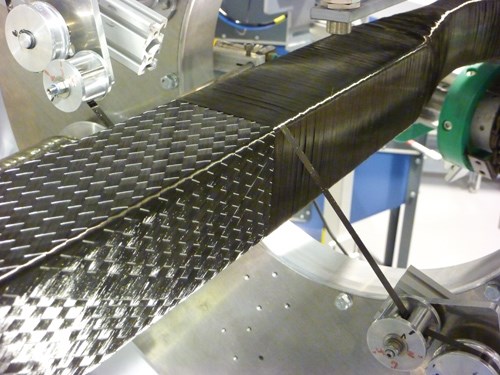
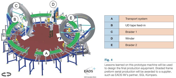
Fig. 4 (at right) shows the demonstrator equipment layout. The transport system is described as being able to clamp with a self-adapting position and span. Both the braiders and the winder are capable of lateral movement, and the winder also features angle correction. This equipment arrangement enables variable frame radii and web heights. It also can fabricate complex frames, including ply drop-offs for braided and 0° UD layers, and integrate local reinforcements (such as those produced by FPP, described later).
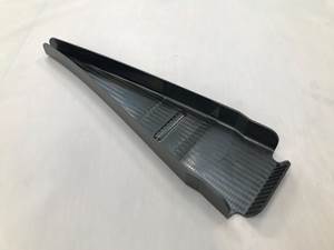
When braiding and winding are complete, the ring of square cross-section preformed fibers is cut in half, and the two C-shaped profiles are removed from the mandrel. The C-shapes, which match the aircraft fuselage diameter as specified, can be shaped further by using a die and an expandable silicone insert to invert one of the C flanges to form a Z-profile. SGL Kümpers reports that BRaF “enables maximum design flexibility and unmatched repeatability to meet the high-volume demands of future aircraft manufacture.”
According to Beaumont, the prototype braided-frame production line is now able to fabricate frames that are fully functional and comparable to frames currently in serial production. “The lessons learned on this prototype machine,” he says, “will be used to design the final production equipment.”
Fiber Patch Preforming
EADS IW and partners Oxeon (Borås, Sweden) and Manz AG (Tübingen, Germany) have developed another process targeted not only for CFRP frames, but also for stringers (longitudinals) and for localized reinforcement for larger composite fuselage panels (e.g., window cutouts and door surrounds). This process is called Fiber Patch Preforming (FPP).
FPP was conceived as a way to automate the production of composite structures that, as a result of topology optimization and other advanced CAD techniques, end up with very complex geometries. Designed to outperform legacy metal structures, these composites feature complex 3-D fiber paths not easily produced using existing technologies, such as prepreg tapes.
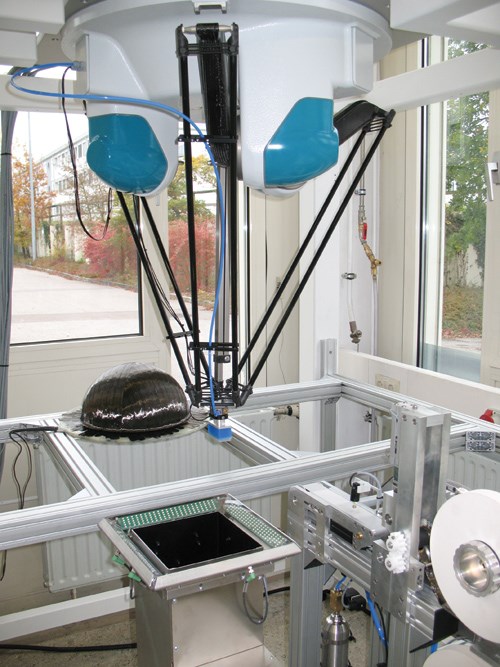
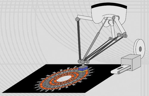
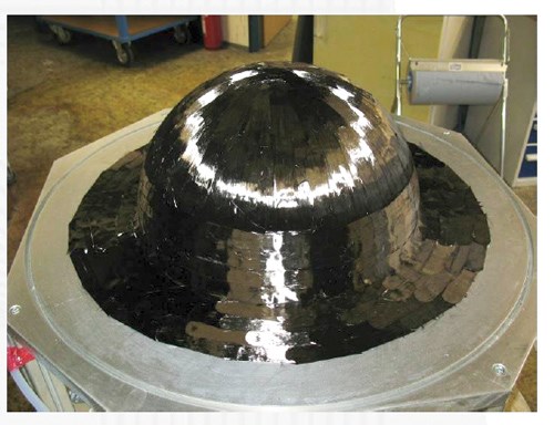
In the FPP process, short (20 mm by 60 mm or 0.79 inch by 2.36 inch) patches of spread-tow unidirectional fiber are cut and then placed by a specialized robot in any direction to construct a dry fiber preform that has a precisely tailored fiber architecture. It retains the conformability required for complex shapes and geometries, without wrinkling or bridging. Robotics reduce production cost without sacrificing precision or producing waste material. The resulting preforms are easy to use in standard resin injection and infusion processes, including resin transfer molding (RTM) and EADS’ patented Vacuum Assisted Process (VAP), and they also may be combined with other types of preforms. (VAP, patented in 2002, is a double vacuum bag resin infusion process in which the inner bag is a gas-porous membrane that allows extraction of volatiles while serving as a resin barrier.)
An FPP dry fiber preform could be used as a local reinforcement for a prepreg structure, using resin from the prepreg or an additional resin film to impregnate the very thin preform (several 100 g/m2 layers) during autoclave cure. Beaumont also cites FPP’s completely 3-D digital process chain as an aid to fabrication robustness: “Beginning with a CAD model of the part, through stress analysis and location of patches, to programming the preform layup robots and then robotic placement, the part’s information is never removed from the digital CAD world.”
FPP in detail
EADS IW’s partners supply the unidirectional reinforcements and robotic equipment. EADS IW developed the FPP robot in-house and has licensed Manz Automation Tübingen to reproduce it. Oxeon furnishes TeXero UD Spread Tow Tapes (all Oxeon products are now sold under the trade name TeXtreme), which feature a thermally activated binder on one side to enable fixation after placement. Beaumont explains that FPP is not limited to spread-tow materials. “We can also use noncrimp fabrics,” he says. “However, our goal was to have a preforming process that was as flexible as possible in the types of geometries it can make. Thus, we use small amounts of fiber per patch, roughly 1g by weight, using 12K tow, and we spread it as flat as we can get it without losing stability, which is about 20 mm [0.79 inch].”
Beefier noncrimp fabrics reportedly limit the possible geometries and shapes due to their greater areal weight and thickness. Thinner reinforcements tend to be more drapable and flexible; they also aid in steering patch to patch — in other words, the direction and location of each patch. “This is the building block of our preform,” says Beaumont. “This is a process for low-volume, high-complexity parts. We are talking lay-down rates of g/hr not kg/hr.”
Although it’s too slow for large parts, the process achieves the tailored fiber designs needed for small parts with complex geometries. “We lose deposition rate because the patches are so small, but we gain flexibility and tailoring, which was our original goal.” Beaumont says that components with a fiber weight of less than 500g are attractive targets for FPP.
Initially, the approach to make such complex preforms was based on advanced fiber sprayup technology, with the goal of having online adjustable fiber length and control of fiber layup angle. However, experiments showed that this process did not achieve the high level of material quality required. Thus, the current technology was undertaken. Short fiber patches were desired, so a specialized mechanical cutting device was developed with the ability to specify cutting length. Lasers were explored as an alternative to mechanical cutting, but they showed no improvement in process or speed. Regarding the size, Beaumont comments, “We have used 20-mm by 60-mm patches up to now, but we are not limited to that size nor shape. We could use triangular patches, for example.”
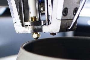
A robotic layup machine picks up the fiber patches and places them as defined by a digital control file. The layup head is made from an elastic material, which makes optimal contact with complex curved surfaces and applies homogeneous pressure as patches are deposited.
Quality assurance (QA) during cutting and layup was an EADS IW concern from the beginning. Beaumont relates, “Quality-control steps were built in throughout its development, not as an afterthought between prototyping and production.” The first step ensures there is no splitting of fibers and the patch shape is correct after it is cut. In the next QA step, the robotic layup machine picks up the fiber patch from the conveyor belt and moves it to a station where a laser device essentially takes a picture of the patch. In real time, the location and orientation of the patch on the robotic stamp is assessed and compared with the CAD layup data. If a correction is necessary, that is communicated to the robot, which then compensates for any variation in the position of the patch on the stamp, adjusting the rotation by the number of degrees required to correct the stamp position as it is placed on the preform. Thus, both the geometry and the position of each patch are checked as an inherent part of the process.
FPP uses a rudimentary steering system. Basically, the robot locates the patch using x, y and z coordinates for both point 1 (the beginning of the patch) and point 2 (the end of the patch) so that only six numbers and a beginning reference are needed to precisely position it. The steering system and QA checks combine to achieve a patch positioning tolerance of ±0.1 mm (±0.04 inch).
When it was discovered that the overlap patterns of the patches significantly affected the strength of the composite preform, a scale-like patch was developed with rounded fore and aft edges to allow inline nesting of patches. The patches also aid in maintaining high strength and stiffness in parts with complex curvature and geometry. The team found that the resulting composites could resist interlaminar delamination and crack propagation. Compared to continuous fiber-reinforced composites, FPP laminates exhibited a small knockdown in strength (14 percent) but practically the same stiffness.
Additional experiments showed failure was mainly due to fiber fracture. Beaumont explains, “With the short, discontinuous fibers in these patches, you would expect failure in between the patches, but the test specimens don’t show this. Failure tests show results that look the same as with continuous fiber laminates.” Impact testing also revealed an ability to absorb relatively high impact energies with small damage areas and high residual compression strength compared to continuous fiber laminates.
BRaF and FPP moving forward
In its early stage, BRaF captured the 2010 JEC Innovation Award for Automation and the Niedersachsen Innovation Award, which was presented at the annual CFK-Valley Stade Convention for developments with a particularly high degree of innovation in lightweight CFRP construction. Notably, the JEC Innovation Award judges predicted that the process would enable composites to compete with metals for adoption in structural airframe components. But the work continues in the form of BRaF II, with the goal of optimizing the overall process, including inline fixation of auxiliary yarn (melt and cooling), automated cutting and refinement of the load and deload station. New mandrel materials also will be investigated, as will inline QA measures, such as fiber monitoring within the winders and braiders, and optical angle detection for braiding layers. Future BRaF material development is targeted at reducing areal weight, improving bearing stress and increasing edge protection against impact.
Technology development will be financed by Airbus for the next two years, leading to qualification and certification of both the frame components and the process. This will push frame certification out to 2013, but it should easily accommodate the onset of A350-1000 component production, ahead of assembly and testing prior to the aircraft’s scheduled 2017 entry into service. Serial production of the braided frame preforms will be awarded to a supplier, such as EADS IW’s partner, SGL Kümpers.
Meanwhile, FPP garnered EADS IW another JEC recognition in the Automation category, this time as a finalist for the 2011 Innovation Awards. And the first application of FPP, stringers, is being developed within the IMac-Pro project funded by the European Commission’s Seventh Framework Program. EADS IW leads the project, targeting at least 20 percent weight savings vs. aluminum profiles, and minimum 5 percent weight reduction with a 45 percent drop in cost vs. prepreg profiles.
Multiple processes are being explored for stringer preform consolidation and cure, including RTM with adaptable elements to compensate for preform settling (thickness reduction), continuous resin injection and high-speed microwave heating. Three demonstrators are planned: (1) a stiffened panel with four precured stringers on a prepreg skin; (2) a stiffened panel with four stringer preforms and textile skin cured simultaneously; and (3) a cargo floor unit consisting of a curved framed profile, a straight crossbeam and z-struts.
Beaumont also sees the potential for FPP to dovetail with BRaF. “FPP is well suited for producing local reinforcements, for example, where floor beams attach to the [fuselage] ring frames,” says Beaumont, “where simply more fiber is needed and in specific tailored layups.” He also sees it as being able to improve reinforcing structures, such as door surrounds. “We do see using local reinforcements in manufacturing the braided CFRP frames targeted for the A350-1000,” Beaumont states, “but whether that process looks like the FPP developed to date or something more primitive, we don’t know.” He adds that FPP for fuselage ring frames may be more streamlined to better suit the needs of manufacturing that product vs. FPP for local reinforcement of fuselage panels, which should exploit more of the process’ expanded capabilities.
Related Content
A new era for ceramic matrix composites
CMC is expanding, with new fiber production in Europe, faster processes and higher temperature materials enabling applications for industry, hypersonics and New Space.
Read MorePEEK vs. PEKK vs. PAEK and continuous compression molding
Suppliers of thermoplastics and carbon fiber chime in regarding PEEK vs. PEKK, and now PAEK, as well as in-situ consolidation — the supply chain for thermoplastic tape composites continues to evolve.
Read MoreASCEND program update: Designing next-gen, high-rate auto and aerospace composites
GKN Aerospace, McLaren Automotive and U.K.-based partners share goals and progress aiming at high-rate, Industry 4.0-enabled, sustainable materials and processes.
Read MoreComposites manufacturing for general aviation aircraft
General aviation, certified and experimental, has increasingly embraced composites over the decades, a path further driven by leveraged innovation in materials and processes and the evolving AAM market.
Read MoreRead Next
A350 XWB update: Smart manufacturing
Spirit AeroSystems actualizes Airbus’ intelligent design for the A350’s center fuselage and front wing spar in Kinston, N.C.
Read MoreAll-recycled, needle-punched nonwoven CFRP slashes carbon footprint of Formula 2 seat
Dallara and Tenowo collaborate to produce a race-ready Formula 2 seat using recycled carbon fiber, reducing CO2 emissions by 97.5% compared to virgin materials.
Read MorePlant tour: Daher Shap’in TechCenter and composites production plant, Saint-Aignan-de-Grandlieu, France
Co-located R&D and production advance OOA thermosets, thermoplastics, welding, recycling and digital technologies for faster processing and certification of lighter, more sustainable composites.
Read More

