Automating NDT for CFRP aerostructures
Robotic laser shearography enables 100% inspection of complex, flight-critical composite structures.
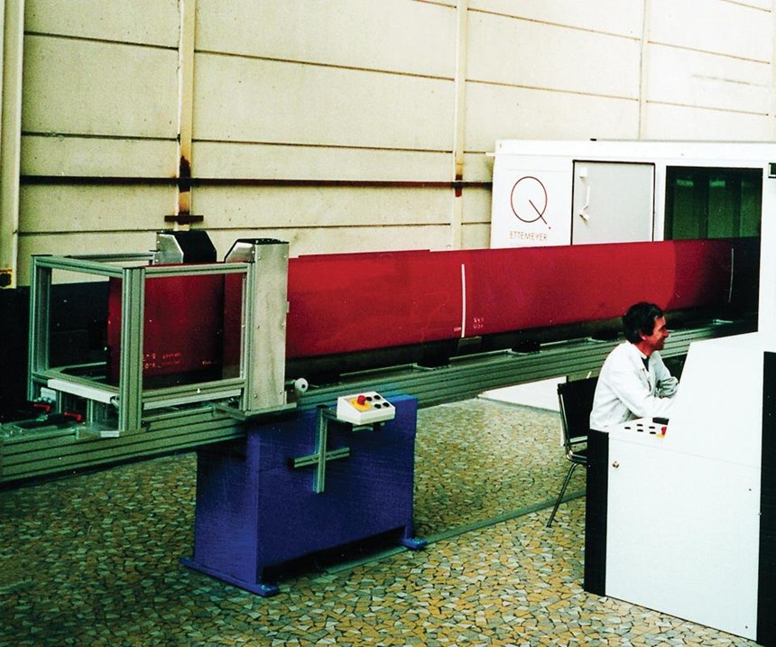
Laser shearography as a nondestructive testing (NDT) method has been used in a production environment for composite structures for two decades and on a variety of aircraft, including the F-22 stealth fighter jet, the F-35 Lightning II, the Cessna Citation X, the Raytheon Premier I, a variety of Airbus aircraft and the NASA Space Shuttles. As a noncontact NDT method, laser shearography is well-suited to automation. In fact, an automated shearographic system was installed almost two decades ago at Airbus Helicopter (then Eurocopter) in La Courneuve, France. Supplied by Dantec Dynamics Inc. (Ulm, Germany) in 1998, it was used to inspect helicopter rotor blades made from composites and was reportedly the first such system used for production control in Europe.
This technology has since been modernized, using modular sensors on computer-controlled robotic arms and advanced software, enabling improved detection, image analysis and defect characterization. These advances offer rapid, 100% inspection of complex composite structures — including helicopter rotor blades, aircraft sub-assemblies and space system components — and enable identification of a wide range of defects: disbonds, delamination, cracks, wrinkles, crushed core, fluid ingress, repair defects, voids, foreign objects and barely visible impact damage.
How shearography works
Originally developed in the late 1970s and first used in the 1980s for inspection of B2 Stealth Bomber composite structures during its production, laser shearography employs some type of excitation — e.g., heat, sound, vibration, vacuum pressure — to make defects inside of a composite “react so that you can ‘see’ them on the surface,” says Andreas Welz, general manager for Dantec Dynamics. The “laser” part of the technique is not a means of such excitation, but instead is used to illuminate the part surface to enable visual capture of the surface deformation landscape and subsequent translation of that visual image into digital data.
The system installed at Airbus Helicopter La Corneuve and, more recently, components Dantec supplied for an automated laser shearography system at Textron Cessna (Wichita, KS, US), both use vacuum as the means of excitation. e latter uses a legacy 1.8m by 1.8m by 6m vacuum chamber, supplied by Laser Technology Inc. (LTI, Norristown, PA, US).
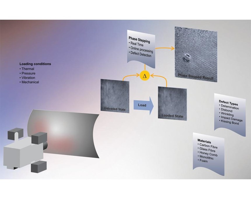
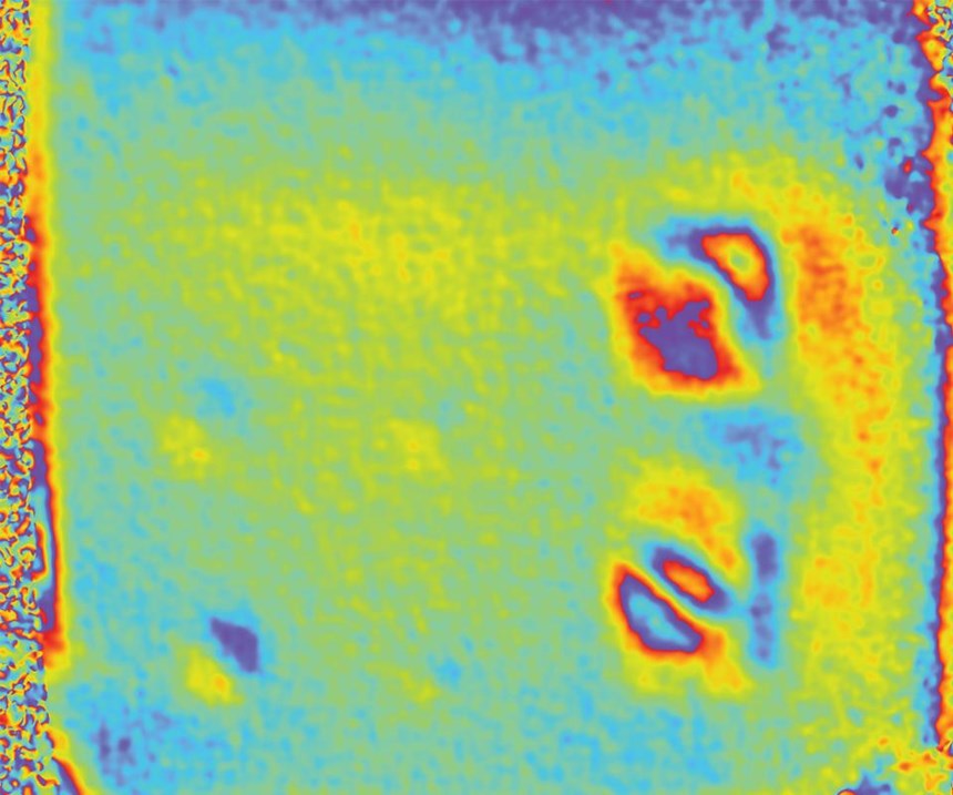
The basic concept behind shearography as a means of testing is to compare an image of the unexcited/unloaded part with one of it excited/under load, and analyze the difference in surface deformation (Fig. 1). Welz explains, “If you apply vacuum pressure to a part, an air bubble inside the laminate, for example, will expand differently vs. the surrounding material.” As the laser illuminates the inspected surface, a camera records the light reflected from it. “The refection pattern of the laser light is like a fingerprint of that surface,” says Welz. Within the camera, a beam splitter and two mirrors create two separate images of the illuminated test area. The position of one image with respect to the other is “sheared” by a prescribed direction and amount (parameters that determine the instrument’s defect sensitivity). The interference pattern between these two images is called a “speckle” and is projected onto the camera’s charge coupled device (CCD), which transforms photons into digital data. The resulting interferometric images and data are used, first, to record the part in an unloaded state, including surface roughness and shape. It then records the part after it is loaded, excited or stressed.
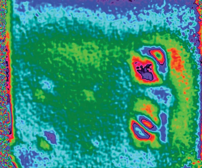
These two images (interferometric fingerprints) are subtracted from each other to produce a shearogram, in which surface deformation is depicted based on the speckle information. Ordinary surface roughness is neglected ad hoc in the subtraction process. Nonhomogeneous areas in the part will present as nonuniform deformation on the surface — a sort of defect topography. “Your defects will be seen as ‘hills’ popping out of the plane,” says Welz. He adds, however, that only gradients are measured — that is, the slopes (i.e., first derivative), not the absolute height of the hills, as is done in holography. “But this enables quantifying the in-plane size of the defects.”
Shearography as a solution
Barend van den Bos is an NDT engineer and project manager with DEKRA Industrial (Linköping, Sweden) who has extensive experience with shearography and composites. He notes that shearography has been used on the carbon fiber/foam cored sandwich construction of the Visby Corvette, a Swedish military ship. “They have inspected the entire ship using shearography,” he points out, “though at the time, it was not automated. They liked it because shearography showed the defects well in the CFRP sandwich, which is difficult to do with ultrasonic testing [UT].” Van den Bos explains that UT struggles with defect detection in bondlines because the soundwave reflection from the core when the bond is not good is too similar to that of a good bond.
“Shearography is one of the few NDT methods that is active, meaning you are stressing the part,” he observes. “So you are stressing this bondline, and can see a difference between good bonds and bad, including defects like kissing bonds.”
Van den Bos first started using shearography at a company called CSM Materialteknik (Linköping, Sweden). “A manufacturer of underground trains for the Stockholm metro came to us with an inspection request,” he recalls. The manufacturer wanted to create an entirely adhesively bonded structure, using sheet steel skins and foam core, and the structure required 100% NDT inspection. “We tried different technologies but shearography was the only one that showed all of the defects they wanted to see,” says van den Bos. So CSM developed the technology and then performed the inspection work.
This is also when van den Bos started working with Dantec. “The technology was not automated then,” he notes, “but we had many square meters to inspect, so we put the equipment on a mobile platform to further increase the inspection speed.” Van den Bos also saw shearography used for production inspection of aluminum honeycomb sandwich rudders for the Saab Gripen fighter jet. “A modification had been made to a section of the rudder which made inspection difficult, and UT was not effective,” he explains, adding that shearography is one of the few NDT methods well-suited for automation. It is a noncontact technique that does not require a water or gel couplant like most UT methods, nor the associated cost and time of couplant application, cleaning and drying of inspected surfaces.
“Shearography is also used because it gives results very quickly,” says van den Bos, “often within seconds.”
According to LTI president John Newman, shearography’s inspection speed is between 3 and 100 times faster than UT. “We’ve demonstrated 100% inspection of an 11m rotor blade within 10 minutes at the Airbus Helicopter facility,” adds Welz, but he points out that the elapsed time can vary, based on the part composition and defect resolution. “The size of the defects that automated shearography systems can find depends upon the threshold set by the operator,” Welz explains. “A common threshold is 25 mm. You can go lower, but less than 8 mm requires a smaller area of detection, so it would take longer.”
Newman asserts further that the time required for an operator to become proficient in shearography — i.e., able to precisely determine defect size, area and location immediately on the test part — is much less than that required for UT. Van den Bos agrees in general, but cautions that formal requirements for NDT training are nevertheless generally very strict, and although certification as a level 2 inspector in shearography requires 20 fewer hours than that for UT, both certificates require 800 hours of experience.
Updated inspection
According to Welz, developments in shearography over the past 20 years have significantly improved defect detection, large-area scanning speed and interactive control and analysis of measurements for more detailed defect characterization. It also has become an increasingly resilient process. As described above, shearography’s defect visualization relies on interferometry. “There are many interferometry technologies, such as holography, which can be sensitive to vibrations,” notes van den Bos. “However, the ‘double image’ method used in laser shearography, together with state-of-the-art fast processors, takes care of this so that modern systems can be used in a wide range of industrial settings, including in-field use.”
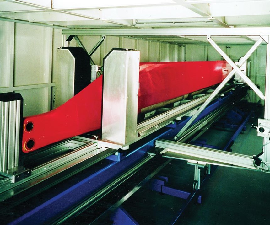
The latest automated laser shearography systems use a 6-axis robotic arm mounted on a rail for rapid scanning of large structures. Because vacuum is one of the most common excitation methods, the robot arm and rail often reside inside an appropriately sized vacuum chamber, for example, 11m long, 5.5m wide and 2m high for helicopter rotor blades. The Windows-based computer-control terminal sits outside.
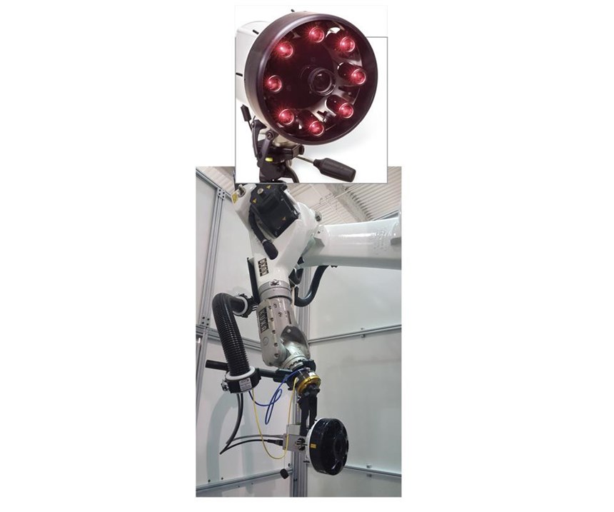
The robot’s end-effector is a shearography sensor head comprising a CCD camera surrounded by eight Class 3R laser diodes (Fig. 2). Commonly used in a variety of industries, diode lasers offer improvements in power and accuracy and emit light over a larger area vs. previous solid-state lasers. They also are less expensive and, because they are safer to use, eliminate previously required safety measures that include operator goggles and system interlocks.
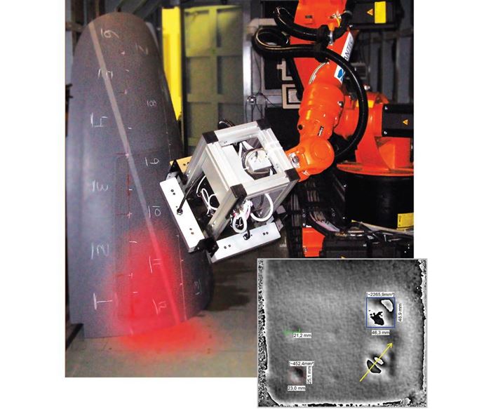
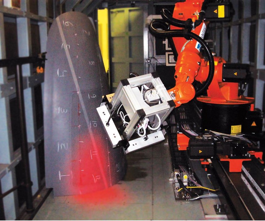
The automated robotic arm that Dantec Dynamics supplied to Cessna (opening image and Step 3) uses a shearography sensor within a large heat excitation frame, which can apply up to 3 kW of heat in addition to the vacuum chamber pressure. Thus, two excitation methods can be used. More recently, Dantec’s robotic systems integrate an even larger variety of excitation tools that are external to the shearography head — modular tools that “plug and play” through system software.
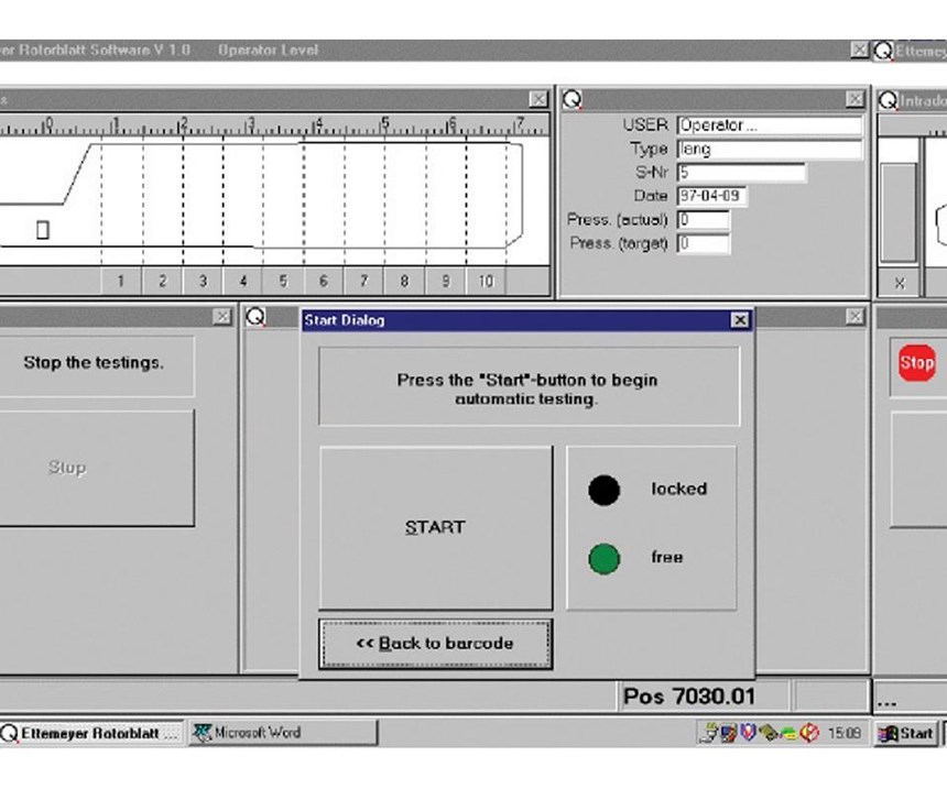
Inspection using a vacuum chamber begins by positioning the structure on a carrier, where it is affixed with automatic clamps. The operator pushes a button to move the carrier into the vacuum chamber (Step 1) and then closes the chamber door. When the operator has called up the program for the specific part (Step 2), the system loads all inspection parameters and releases the robot to identify the specimen, either by reading a bar code or confirming an operator-entered part number.
The robot then moves to the first location to be inspected, shines the lasers and takes an image of the unloaded part (Step 3). It then applies a partial vacuum of less than 50 mbar. “If you have a thicker part or if you’re looking for a deeper defect, you will need more pressure difference or heat to provide sufficient excitation,” explains Welz. “If the operator doesn’t need to know as much, then he or she can set the parameters accordingly.” He also notes that material construction plays a factor, “For example, glass and carbon fiber monolithic structures often require heat excitation, while sandwich construction responds well to pressure loading.”
After vacuum excitation is applied, the robot again shines laser light on the surface, measures the reflection and saves the data. The operator then can interact with the excitation tools and sensor head to fine-tune the stress applied, images received and resulting defect characterization. The robot then moves on to the next position and repeats the procedure until unloaded and loaded images have been captured and compared for all surface locations in the selected part program (Step 4).
During this process, if a defect is detected, a laser pointer on the robot will show where the defect is on the actual part. The operator then can enter the vacuum chamber and mark that area. is function also can be automated. For example, Carl Zeiss Optotechnik (Neubeuern, Germany) can reportedly integrate a laser tracker so that positional data is incorporated into the laser shearography scan, documenting defect locations.
Digital development
Continued advancement in digital technology is making laser shearography systems even easier to use on complex composite structures in a production environment. For example, Dantec Dynamics’ most recent Istra4D software provides improved image filtering and image quality for unambiguous results that are easily reproducible, and new post-treatment features allow for more detailed defect information. It also is possible to design standard reports, into which recorded system parameters and results from inspection sessions are loaded automatically. Thus, new inspections can be automatically compared with previous inspections and results included in the templated report. The system also can be trained to intuitively evaluate the structural integrity of composites with ply drops, bulkheads, overlaps, splices, stringers and ribs, etc.
As composites manufacturing matures and production rates continue to increase, NDT systems that can be integrated inline and achieve 100% inspection will be key. Automated laser shearography offers a potentially efficient and customizable means to attain that capability.
Related Content
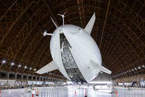
Next-generation airship design enabled by modern composites
LTA Research’s proof-of-concept Pathfinder 1 modernizes a fully rigid airship design with a largely carbon fiber composite frame. R&D has already begun on higher volume, more automated manufacturing for the future.
Read MoreInfinite Composites: Type V tanks for space, hydrogen, automotive and more
After a decade of proving its linerless, weight-saving composite tanks with NASA and more than 30 aerospace companies, this CryoSphere pioneer is scaling for growth in commercial space and sustainable transportation on Earth.
Read MoreWelding is not bonding
Discussion of the issues in our understanding of thermoplastic composite welded structures and certification of the latest materials and welding technologies for future airframes.
Read MoreCombining multifunctional thermoplastic composites, additive manufacturing for next-gen airframe structures
The DOMMINIO project combines AFP with 3D printed gyroid cores, embedded SHM sensors and smart materials for induction-driven disassembly of parts at end of life.
Read MoreRead Next
Plant tour: Daher Shap’in TechCenter and composites production plant, Saint-Aignan-de-Grandlieu, France
Co-located R&D and production advance OOA thermosets, thermoplastics, welding, recycling and digital technologies for faster processing and certification of lighter, more sustainable composites.
Read More“Structured air” TPS safeguards composite structures
Powered by an 85% air/15% pure polyimide aerogel, Blueshift’s novel material system protects structures during transient thermal events from -200°C to beyond 2400°C for rockets, battery boxes and more.
Read MoreAll-recycled, needle-punched nonwoven CFRP slashes carbon footprint of Formula 2 seat
Dallara and Tenowo collaborate to produce a race-ready Formula 2 seat using recycled carbon fiber, reducing CO2 emissions by 97.5% compared to virgin materials.
Read More

