
Composites stabilize space-based telescope
Composite Primary Mirror Backplane Support Structure to hold James Webb Space Telescope’s thermal stability within extremely tight 38-nm dimensional tolerance.


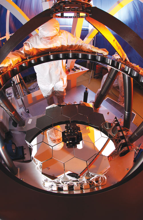
The Backplane configuration interfaces with the 18 planar hexagonal sections of the primary mirror, shown here in a fully functional, 1/6th-scale model. Source: NASA
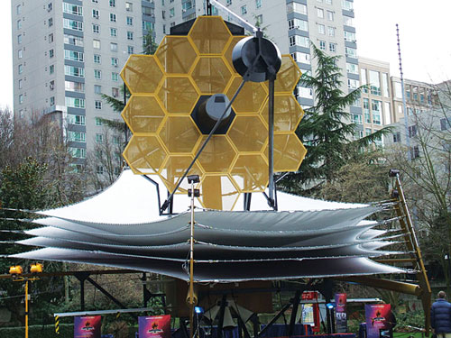
A model of the James Webb Space Telescope, shown while on display in Seattle, Wash. Source: ATK
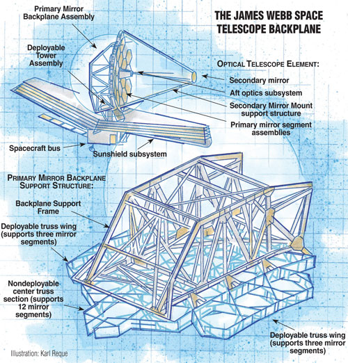
Illustration: Karl Reque
Design Results:
¤ FEA process for JWST composite Backplane converts materials design analysis into an FE model with 14 million degrees of freedom.
¤ Coupons made from modeled carbon composite prepreg are tested and validated for cured design properties, including ±38 nm dimensional stability.
¤ A low-mass subscale truss structure, built to design using four-sided hollow tubes made with prepreg in various architectural laminates, is subjected to cryogenic testing, confirming the Backplane’s dimensional stability.


The basic composite structural building blocks of the satellite industry debuted in the late 1970s and early 1980s, but NASA’s specifications for the James Webb Space Telescope (JWST) set forth unprecedented — and nonnegotiable — requirements. Also responsible for fabrication and assembly of the JWST’s Integrated Science Instrument Module (ISIM), the Secondary Mirror Mount (SMM) and composite components that comprise the Deployable Tower Assembly (DTA), subcontractor ATK Space Systems (Magna, Utah) confronted a particularly formidable challenge in the Primary Mirror Backplane Support Structure (see drawing, top right). As the primary load-carrying cornerstone of the Optical Telescope Element (OTE) and its 6.6m/21.65-ft diameter primary mirror array, the Backplane is responsible for holding the telescope perfectly stable at cryogenic temperatures during long periods of light collection. “JWST will be operational for 14 days at a time, collecting the very faint light particles from the beginning of time,” explains Bob Hellekson, ATK’s JWST program manager, “and the telescope must remain perfectly stable while the observatory is in a science/light collection episode for the maximum science benefit.”
NASA defined perfectly stable as within 38-nm thermal stability. A nanometer is one-billionth of a meter or one-millionth the diameter of a human hair. Therefore, the JWST structure must not vary dimensionally more than ~1/10,000th of the thickness of a sheet of paper. “That is a pretty small number for a thermal stability requirement over 14 days on a structure the size of a one-room schoolhouse,” Hellekson says.
The 11.3m/37-ft high, 12.1m/40-ft wide and 19.2m/63-ft long JWST will succeed the 17-year-old Hubble Space Telescope. While Hubble has captured mainly visible light, the JWST will primarily observe infrared (IR) light from faint and very distant objects, using four scientific instruments designed to work primarily in the IR range of the electromagnetic spectrum. To avoid interference from IR light generated by its own heat, the telescope and its instruments must be very cold and, therefore, will be protected by a large sunshield from exposure to any significant light source — Earth, Sun or Moon — which could increase the telescope’s temperature and interfere with observations. The JWST’s position in space certainly will qualify for very cold: Its operating temperature will be about 19°K (-254°C/-425°F) in its elliptical orbit almost a million miles from Earth (932,057 miles/1.5 million km). During its trip into space, the JWST structure also must endure bulk cooldown from room temperature at takeoff of about 293°K (19.85°C/67.73°F).
In addition to thermal stresses, the JWST will be subjected to most of the hazards endured by satellites. These will include significant aerodynamic and launch forces, notably vibration, acoustic and bending loads. Because all of space is a vacuum, its composite materials must be vacuum-compatible to avoid outgassing of absorbed water or material constituents, which could change the material properties and performance. Although the JWST’s sunshield will protect it from the Sun’s light, and its distance from Earth will eliminate atomic oxygen (AO) degradation as a factor (satellites in low Earth orbit or LEO, 124 miles/199.5 km to 1,240 miles/1,995.5 km above Earth’s surface, must contend with AO), it will encounter other hazards: JWST could suffer impact by the occasional micrometeoroid and, in orbit outside the protection of the Van Allen belts, will be exposed to the galactic cosmic radiation (GCR) environment. All this must be factored into any satellite design, within the lowest possible mass.
Meeting the challenge
Based on previous developmental studies, ATK was confident that the challenge could be met. Under the oversight of NASA Goddard Space Flight Center (Greenbelt, Md.) and prime contractor Northrop Grumman Space Technology (Redondo Beach, Calif.), ATK contracted for design, analysis, fabrication, assembly, inspection and testing of the Backplane.
ATK began with characterization of basic raw material constituents to help produce engineering finite element analysis (FEA) modeling and design analysis. ATK says it has “developed the most accurately validated, large FEA model in our history at over 14 million degrees of freedom” (DOF, the displacements and rotations that can occur at each node, or discrete point in the structure, which together form the modeled shape). Based on the analysis and modeling, composite coupons were built to represent the models and were tested for the design properties. “An engineering mo-del of this size and complexity,” explains Hellekson, “allows for explicit representation of each of the ±8,000 piece parts and the individual adhesive bond layers — all of which are necessary for nanometer-level thermal distortion predictions.”
As a result of its painstaking design analysis, ATK is using unidirectional prepreg made from M55J carbon fibers (Toray Carbon Fibers America Inc., Flower Mound, Texas) and HexPly 954-6 cyanate ester resin (Hexcel, Dublin, Calif.). For some prepreg parts, Toray T300 fabric is used with 954-6 resin. “The 954-6 system was selected for its performance at cryogenic temperatures, which is enabled, in part, by its 250°F/121°C cure in a pressurized autoclave,” says Kevin Patton, ATK’s JWST lead design analyst. “This is 100°F lower than many traditional space resins and therefore provides lower residual component material stress when cooled down [to 19°K/-425°F/-254°C]. Hexcel has worked very closely with ATK to provide a product [that has minimal] thermal expansion properties.”
These basic materials are combined in three primary laminate “families” to meet changing thermal and structural stresses over the entire Backplane, top to bottom. The bottom of the Backplane is the warmest region, where it attaches to the Deployable Tower Assembly (DTA) and is nearest the sunshield. The top, at the opposite end, is the coldest region. The design of each laminate family varies from the others to accommodate the progressively different thermal stresses in each region. “Though thermal stresses are much different from top to bottom, the truss as a whole will provide the specified on-orbit nanometer stability,” confirms Marcel Bluth, ATK JWST systems engineer.
Similarly, the structural loads vary, with higher loads applied where the Backplane attaches to adjoining components of the OTE. The Backplane itself is a tube truss configuration comprising four individual truss sections: (1) a nondeployable center section that supports 12 of the mirror segments; (2) left and (3) right deployable truss wings, each supporting three of the remaining six mirror segments; and (4) the Backplane Support Frame (BSF). The BSF is essentially a torque box for backing up the strength and stiffness of the Backplane and OTE.
The four-sided tubes are designed in more than 50 combinations of wall thickness, shape and dimension: rhomboid shapes; square tubes up to 2.5 in2/1,613 mm2 in cross-section, with walls as thin as 0.040 inch/1.02 mm; and rectangular tubes up to 4 inches by 7 inches (101.6 mm by 177.8 mm) in cross-section, with walls as thick as 0.170 inch/4.32 mm. “The various laminate families provide stronger and stiffer tubes with thicker cross-section where needed and more mass-efficient tubes in thinner cross-section where allowed,” Bluth explains.
The final geometric configuration of the Backplane conforms to the 18 planar hexagonal sections of the primary mirror, with which the Backplane interfaces. At a total mass of <1,000 kg/<2,205 lb, the Backplane supports three times its own weight through its interface with the mirrors, the science instruments and the JWST ISIM.
Building the Backplane
To build the Backplane tubes, prepreg is hand layed in the appropriate laminate schedule over aluminum mandrels that were pretreated with a release agent and cured at 250°F/121°C to form lengths of composite tubing, which can be machined later into multiple parts. The tubing lengths are visually and ultrasonically inspected and tested for mass, cured laminate thick-ness, interlaminar strength properties, dimensional tolerances and overall profile and flatness, thermal expansivity (from room temperature to cryogenic temperature), tangent coefficient of thermal expansion (CTE) at cryogenic temperatures and more. ATK established a special CTE facility in San Diego, Calif., that is providing precision (parts per billion) cryogenic composite and material metrology to meet the stringent resolution and accuracy requirements. Following inspection, the tubing lengths are cryogenically conditioned at ATK’s Logan, Utah facility by cycling them five times from room temperature to 25°K/ -415°F/-248°C. After cryo-conditioning, another ultrasonic inspection confirms piece-part dimensional accuracy to the drawings. After passing QA procedures, the tubing lengths are machined into final flight-configuration components, with individual tube serial numbers.
To form the truss, tube sections are bonded together by several different methods, which are selected according to the engineering analysis. The most highly loaded areas make use of Invar metallic fittings bonded directly to the composite. Composite tubes are bonded into the final assembly using flat plate M55J/954-6 Hexcel prepreg composite gussets and angle clips and Henkel Aerospace’s (Bay Point, Calif.) Hysol EA 9309.2NA, a nonasbestos two-part paste adhesive with high shear strength and high peel strength.
The backplane is kinematically mounted to the ISIM. That is, it attaches by means of composite support struts that are arranged in a pseudo-bipod architecture and can be individually flexed to reduce on-orbit loads trans-mitted between the two structures. The struts are similar in construction to the Backplane tubes, but boron and high-modulus pitch fiber are used in some of the mounting tubes.
A full-scale substructure Backplane Stability Test Article has been subjected to cryogenic testing at NASA Marshall Space Flight Center (Huntsville, Ala.). Results have confirmed that the final flight design will perform within the 38-nm thermal distortion specification. “The ATK composite Backplane will not vary in its dimensional stability over the 14-day light collection periods, while thermal gradients and excursions exist on the observatory,” Hellekson affirms.
Scheduled for launch mid-2013, the JWST is designed for a minimum five-year life cycle. However, citing the proven, long-term performance of composite structures on the Hubble and other space structures, ATK fully expects the Backplane and its other JWST composite structures to survive much longer.
Adding value to the industry
Technologies developed specifically for the JWST mission are expected to impart value to the entire satellite industry, notably through a new cryogenic materials database developed during ATK’s extensive FEA and CTE cryogenic composite studies and material metrology work. Additionally, future satellite programs will benefit from ATK’s nanometer-scale thermal distortion modeling predictions, its methods for deployment of telescope mirror subsystems, and lessons learned about bond tolerances and the production of low-mass structures.
The composites industry — along with the rest of the world — will no doubt closely follow the progress of this amazing undertaking, keenly interested in both the performance of the materials and the ultimate findings of this unique observatory.


Read Next

VIDEO: High-volume processing for fiberglass components
Cannon Ergos, a company specializing in high-ton presses and equipment for composites fabrication and plastics processing, displayed automotive and industrial components at CAMX 2024.
Read More
Developing bonded composite repair for ships, offshore units
Bureau Veritas and industry partners issue guidelines and pave the way for certification via StrengthBond Offshore project.
Read More
All-recycled, needle-punched nonwoven CFRP slashes carbon footprint of Formula 2 seat
Dallara and Tenowo collaborate to produce a race-ready Formula 2 seat using recycled carbon fiber, reducing CO2 emissions by 97.5% compared to virgin materials.
Read More