Compression molding with structural carbon SMC
Aircraft weapon system gains the high performance of carbon/epoxy with the efficiency of compression molding.
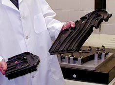
When engineers at General Dynamics Armament and Technical Products (GDATP) recently designed the ammunition container for a new aircraft weapon system, they decided very early in the process to make the container's side panels from a carbon fiber/epoxy sandwich structure with continuous-fiber laminates and aluminum honeycomb core. The choice allowed this division of General Dynamics (Charlotte, N.C.) to meet "the extremely aggressive size and weight restrictions that were imposed on the design, while maintaining adequate structural stiffness," reports Peter Wolff, GDATP's project engineer for aircraft systems. That choice imposed engineering challenges that included development of panel edge closeouts and mechanical joints between the panels that were compatible with the panels' thermal expansion properties, to survive severe operating temperatures on the aircraft. But even more challenging was the manufacture of the weapon system's cartridge guides, complex parts in two sizes (approximately 200 mm/8 inches square and 300 mm/12 inches square), with curved vertical walls that form the channels through which ammunition rounds travel enroute from the container box to the weapon's firing chamber.
Carbon/epoxy was the preferred material choice for the ammunition guides because it would meet the weight restrictions and match the thermal properties of the container's carbon/epoxy side panels. Additionally, carbon/epoxy offered superior wear resistance, compared to metals, and would provide better vibration damping and fatigue resistance when jarred by ammunition rounds cycling at high-speed through each guide. But the appeal of carbon/epoxy was tempered by the design's processing challenges. Conventional aerospace practice would be to hand lay the parts with prepreg. The cartridge guides, however, range in thickness from 3mm/0.120 inch to more than 25 mm/1 inch, and these thicknesses must be controlled to within 0.127 mm/0.005 inch. Therefore, if it even proved possible to hand lay such subtle thickness differences, the ply schedule for the complex, curved ammunition pathways would require a large number of specially cut pieces -- 100 or more -- to create each cartridge guide. As a result, the cutting, kitting and layup processes would be both tedious and labor-intensive, raising costs significantly. Automating as much of the molding process as possible became a priority. But in what form would carbon/epoxy enable engineers to achieve the desired level of dimensional accuracy and do so cost-effectively, given the parts' complex geometry? "It would be difficult with this complex shape to use prepreg cloth or resin transfer technology without having resin-starved or resin-rich areas, compromising performance," observes John Willig, VP for technology, Parkway Products Inc. (Erlanger, Ky.), the molder for the project.
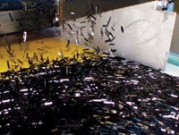
For these reasons, General Dynamics and Parkway investigated compression molding, a process specialty for Parkway for more than five decades, using Lytex 4149 Engineered Structural Composite, a carbon fiber-reinforced, structural-grade epoxy sheet molding compound (SMC) previously developed by Quantum Composites Inc. (Bay City, Mich.). Manufacturers of high-performance components commonly perceive SMC (typically compounded from chopped glass fiber and polyester resin) to be a commodity material, used primarily in nonstructural components. But Quantum reports that Lytex 4149 offers finished properties that approach those ofcarbon/epoxy prepregs. The material is compounded with 25-mm/1-inch 3K PAN-based carbon fibers (55 percent by weight) wet out with Lytex epoxy resin originally created by Morton Thiokol (now ATK Thiokol, Salt Lake City, Utah) to optimize moldability. Quantum Composites now owns this formulation.
Changing paradigms
Because it marries the performance of carbon fiber with the manufacturability inherent in compression molding, Lytex 4149 presents some unfamiliar processing challenges. On the one hand, engineers experienced in fabricating carbon/epoxy components often are unacquainted with SMC and the finer points of compression molding. Experienced compression molders like Parkway, on the other hand, have enjoyed some processing latitude when working with conventional glass-reinforced SMC. Conventional SMCs feature fiber loading of only 22 to 30 percent by weight, and their polyester resins exhibit favorable flow characteristics. Structural-grade SMCs like Lytex, with fiber loadings of 50 to 70 percent, offer less latitude. To take advantage of the performance benefits of structural SMCs, therefore, fabricators must carefully craft and control the compression molding process. In this case, the areas most critical to process control were mold design and the design and placement of the charge.
Mastering the mold
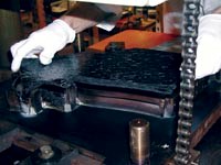
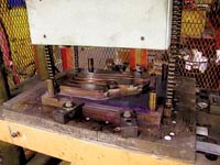
Molds for the project were made with H-13 high-grade, high-hardness tooling steel, to resist the abrasion from the high carbon loading. Mold design was critical, in part, because "if you don't get it right the first time, changes are expensive," notes Mickey Dalton, Parkway's project manager. Further, the part design made demolding difficult. "General Dynamics likes to work with minimum draft -- no taper on the walls. But most compression-molded components have a draft of 1° to 3°," Dalton explains. "On this project, we accommodated a 0° draft." The lack of taper makes it difficult to remove the cured part from the mold, especially with materials such as Lytex 4149, which experience very little shrinkage (less than 0.001 inch/inch). The cartridge guides also required a flatness profile of only 1.27 mm/0.050 inch to 2.03 mm/0.080 inch; consequently, almost no distortion could be tolerated during demolding. Parkway accommodated the lack of draft and low distortion tolerance by incorporating ejector pins into the mold design, using an unusual chain-eject mechanism. As the press opens, ejector pins automatically and mechanically move in to release the component from the mold. To prevent any distortion or stress fractures, Parkway engineers developed a precise ejection sequence, adding extra ejection pins and strategically modifying the length of certain pins by 0.076 mm/0.003 inch to 0.127 mm/0.005 inch so that they pushed on selected areas in stages. This approach has achieved flatness profiles better than required, ranging between 0.76 mm/0.030 inch and 1.27 mm/0.050 inch.
Mold design proved difficult because of the material's high fiber loading. "While the material has to flow into some of the corner and rib locations," Willig says, "you really want to minimize the amount of material flow." Flow lines in structural SMCs, especially in critical areas, can compromise the component's properties. Tools must be designed in a way that "ensures you don't get flow lines in critical strength areas," reports Quantum Composites technical services manager Mike Kiesel. He explains that the performance "delta" -- the difference between the reduced strength of a material along a flow line and the baseline strength in the portion of the material that experiences comparatively little movement -- is greater in a structural SMC because of the much greater original material strength. In a nonstructural grade SMC with its lower fiber loading, the original material strength is closer to the low strength of a flow line. Parkway engineers therefore considered flow lines very deliberately, using empirical data charts on material shrinkage and flow, developed by the company, as they drafted the mold CAD/CAM models.
Step 1
Step 2
Step 3
Step 4
Step 5
Step 6
Step 7
Step 8
Building the charge
Parkway met anticipated mold-flow challenges by minimizing material flow through careful design and placement of the charges. In fact, the effort required to create a charge pattern for the cartridge guides was unprecedented at Parkway. "We don't make anything with this complexity out of any other compression-molded material," comments Dalton. "How you lay this material in the mold controls how the part comes out." Areally, the material covers over 95 percent of the mold, compared to conventional SMCs charges that typically cover 50 to 90 percent. This high coverage not only accommodates the high viscosity of the material, it also maintains the integrity of the reinforcement. "If you get the material to flow too much," Willig notes, "the fiber starts to break up into shorter-lengths that don't orient along flow lines as well as the full-length fibers, so you don't achieve the desired mechanical properties."
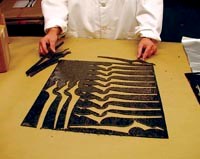
Build-ups for the ribs and thicker areas of the components require numerous plies, and the curved ammunition pathways being created by these build-ups mean that some ply shapes involve intricate curvatures. The 15.9-mm/0.625-inch thick Lytex 4149 must be stacked up several layers high, to flow properly into perpendicular walls. These walls are up to 25.4 mm/1 inch high and as little as 15.9 mm/0.625 inch wide. "If you didn't have a predetermined stack sequence, material would flow up that wall in ways we can't predict," Willig points out. "We need to know that fibers are positioned accurately within these walls to hold dimensions and achieve mechanical strength."
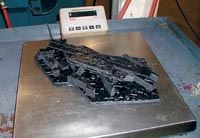
Parkway engineers determined the volume and calculated the weight of each component to provide a starting point for the charge weight. After creating a rough charge pattern, Parkway ran a less expensive, glass-based material to test the fabricating process. "With all the variables, no computer programs are available to simulate the flow or forming process," Dalton notes. The empirical data acquired with the inexpensive trial runs guided modification of the charge pattern for the best outcomes. The resulting charge consists of more than 30 pieces cut from the 15.9-mm/0.625-inch thick Lytex 4149 sheets. Although Lytex has greater B-stage stiffness than glass/polyester SMCs, due to the use of epoxy and higher fiber loading, the materials can be cut with the same tools. Depending on each pattern shape and the cost-effectiveness of creating a stamping die, some pieces are die cut while others are cut using a band saw.
Handling with care
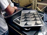
Long-fiber carbon/epoxy SMCs exhibit some unusual characteristics that added several steps to Parkway's fabrication process. First, like prepreg, the sheets of Lytex 4149 must be stored in a freezer, then removed and warmed to room temperature before pieces can be cut, stacked and weighed for quality assurance -- a step not required with conventional polyester SMC. Second, because epoxies must be preheated prior to compression molding, pieces for each preform must be layed out on oven sheets and placed in a 99°C/210°F oven for one to two minutes. A conventional convection oven is used because dielectric or microwave heating cannot be performed on carbon-filled materials.
Parkway coats the mold with Sprayon S00311 PTFE (Diversified Brands, Cleveland, Ohio) or Nix Stix X-9032 (Dwight Products Inc., Lyndhurst, N.J.) mold release. The mold is positioned in a conventional compression molding machine and heated to 150°C/300°F. The preform must be transferred quickly to allow the press to be closed within 90 to 120 seconds. Therefore, two operators work in tandem, and they stack some ply build-ups, perhaps five pieces of the preform, outside the mold before positioning these pieces all at once. Hydraulics then close the mold, and the part cures for 8 to 10 minutes under 689.5 bar (5 tons/in2) of pressure. No postcure is required. Demolded parts cool for about an hour before they are trimmed and quality-checked for thickness and flatness. Finally, mounting and bearing holes are drilled with carbide or diamond tools supplied by OSG Tap and Die Inc. (Glendale Heights, Ill.) -- chamfered lead-ins for these holes are molded in -- and finished parts are packaged and shipped to General Dynamics for assembly with the rest of the weapon.
Enjoying the fruits
Parkway currently makes a dozen parts for each weapon, of which the largest and most complex are the four cartridge guides. Eighty sets have been made to date, and Parkway's contract calls for delivery of an additional 82 sets over the next two years.
Lytex 4149 versions of the cartridge guides weigh about half as much as aluminum counterparts and about 30 percent as much as the same part in stainless steel (910g/2 lb for the two smaller cartridge guides and 1,590g/3.5 lb for the larger). Component cost also came in at a satisfactory level. While Lytex 4149 costs significantly more than typical unidirectional carbon/ epoxy prepreg, the total manufacturing cost of such complex parts -- when fabrication from a prepreg is even feasible -- is often lower with the structural SMC. In the case of the cartridge guides, costs were low because the complex geometries, according to Wolff, "could be molded to net shape to the required tolerances, thus eliminating a significant amount of machining and minimizing the number of parts in the assembly. The use of Lytex 4149 for the cartridge guides allowed General Dynamics to meet its cost objectives."
Related Content
Combining multifunctional thermoplastic composites, additive manufacturing for next-gen airframe structures
The DOMMINIO project combines AFP with 3D printed gyroid cores, embedded SHM sensors and smart materials for induction-driven disassembly of parts at end of life.
Read MorePlant tour: Joby Aviation, Marina, Calif., U.S.
As the advanced air mobility market begins to take shape, market leader Joby Aviation works to industrialize composites manufacturing for its first-generation, composites-intensive, all-electric air taxi.
Read MoreLarge-format 3D printing enables toolless, rapid production for AUVs
Dive Technologies started by 3D printing prototypes of its composite autonomous underwater vehicles, but AM became the solution for customizable, toolless production.
Read MoreA new era for ceramic matrix composites
CMC is expanding, with new fiber production in Europe, faster processes and higher temperature materials enabling applications for industry, hypersonics and New Space.
Read MoreRead Next
Developing bonded composite repair for ships, offshore units
Bureau Veritas and industry partners issue guidelines and pave the way for certification via StrengthBond Offshore project.
Read MoreVIDEO: High-volume processing for fiberglass components
Cannon Ergos, a company specializing in high-ton presses and equipment for composites fabrication and plastics processing, displayed automotive and industrial components at CAMX 2024.
Read MorePlant tour: Daher Shap’in TechCenter and composites production plant, Saint-Aignan-de-Grandlieu, France
Co-located R&D and production advance OOA thermosets, thermoplastics, welding, recycling and digital technologies for faster processing and certification of lighter, more sustainable composites.
Read More


