Dual-laminates: Scaling up to scrubbers
A double-protection strategy for this massive fiberglass vessel tests pushes the limits of this shop’s fabricating and logistical planning skills.
Composites have established a solid market position in corrosive applications and are generally recognized as the most cost-effective anti-corrosion materials in the industrial chemical industry. But, occasionally even chemical-resistant fiberglass needs help, in very severe service. That’s where dual-laminate vessels come in: a tough thermoplastic liner on the inside of a fiberglass-reinforced polymer (FRP) structure provides double protection. That’s particularly true in critical applications, especially when project size and scale make titanium, stainless steel or high-nickel alloy solutions cost-prohibitive, says Brian Linnemann, VP of operations at RL Industries Inc. (Fairfield, Ohio), the only company currently certified for both FRP and dual-laminate construction by the American Society of Mechanical Engineers’ (ASME) RTP pressure vessel design code.
“Dual-laminate construction takes advantage of the best elements of thermoplastics and thermosets,” he explains, “and can stand up to the most aggressive environments.”
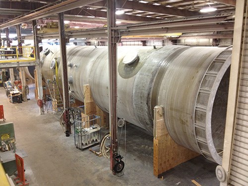
RL Industries recently completed a massive dual-laminate scrubber vessel that will remove pollutants from emissions at a chemical plant owned by a Middle Eastern client. “This project offered many technical and logistical challenges,” Linnemann recalls. Not the least of these was the vessel’s size. The tall, slender scrubber was to be 108 ft/33m tall and 18 ft/5.5m in diameter. Although RL Industries has the capability and equipment to build a vessel of this size on site at a customer’s facility, the complexity of dual-laminate fabrication and the customer’s requirement that the vessel be subjected to acoustic emission monitoring during hydrotesting dictated in-shop fabrication.
Dual-laminate from the inside out
RL Industries’ experienced engineering team developed the vessel’s design in-house. Initial drawings and modeling were done in Solidworks, supplied by Dassault Systèmes Solidworks Corp. (Concord, Mass.), and refined with PTC MathCAD software, from PTC Corp. (Needham, Mass.), and ALGOR’s (Pittsburgh, Pa.) finite element analysis (FEA) tools. The vessel’s strain-based design, as well as the fabrication, testing and inspection procedures, were governed by The American Society of Mechanical Engineers’ (ASME) Boiler and Pressure Vessel Code, Section X on composite vessel design, as well as ASME’s design code, ASME RTP-1, Reinforced Thermoset Plastic Corrosion-Resistant Equipment.
“We used industry-accepted techniques and best practices, and typical pressure vessel design equations,” says Linnemann. “The FEA analysis results showed that our initial design was up to the task and required only minimal changes.”
The design called for four primary components: 1) an upper “shell” or cylinder with a domed “head,” 2) a middle or central shell, 3) a lower shell, also made with a domed head and 4) a “skirt” or supporting structure around the bottom shell that would enable the scrubber to stand upright. The shells and skirt would be filament wound, while the domed heads would be fabricated via vacuum infusion. Complicating the design was the need for internal, circumferential “ledges” or shelves to support tray assemblies in service.
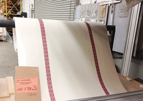
The fabrication process started with the liner. “Lined steel, which has some parallels to dual-laminate construction, is made by ‘wallpapering’ the inside of a completed steel vessel with the thermoplastic,” notes Linnemann, but he explains that “for a dual-laminate vessel, we form the thermoplastic liner first.” The company obtains rolls of the plastic liner material that are 4 ft/1.25m wide and typically 0.090 to 0.157 inch (2.3 to 4 mm) thick, from a range of suppliers: “There are a number of thermoplastic materials that we use, depending on the project, from polypropylene to polyvinylidene fluoride [PVDF] up to high-end, fully fluorinated polymers,” he explains. For the scrubber project, RL’s client chose a high-end, corrosion-resistant ETFE (ethylene tetrafluoroethylene, tradenamed Tefzel) supplied by E.I. DuPont de Nemours and Co. (Wilmington, Del.). DuPont delivered the raw ETFE to Quadrant Engineered Plastic Products AG (Quadrant EPP, Lenzburg, Switzerland), where it was extruded into rolls of sheet material for the project.
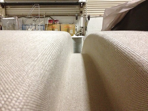
ETFE’s nonstick characteristic makes it very difficult to adhere or bond it to other materials. Quadrant EPP, therefore, supplied the thermoplastic with a lightweight, knitted fiberglass fabric partially embedded into the plastic on the backside to provide a lamination-friendly surface for layup. Prior to fabrication, every lot of the ETFE lining material was tested by RL Industries in accordance with procedures set down in ASTM D 1781, “Standard Test Method for Climbing Drum Peel for Adhesives,” to verify that the embedded glass fabric would provide an adequate mechanical bond to the composite laminate, says Linnemann. The minimum acceptable peel strength is 65 inch-lb/inch, which exceeds the minimum specified by ASME RTP-1, Appendix M12. In fact, RL Industries dispatched engineers to Switzerland to witness liner extrusion and peel testing before the rolls were shipped to Ohio.
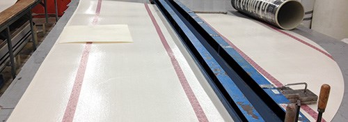
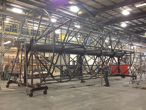
After its arrival at RL Industries, the rolled ETFE liner material was cut into sheets and then was flow fusion-welded to portions of the scrubber’s liner. Flow fusion-welding involves a welding machine, which clamps, heats and fuses the butted edges of the thermoplastic sheets, explains Linnemann: “The thermal expansion of the sheet drives the edges together.” For the three cylindrical shell sections, sheets were welded to form tubular sleeves except for the final weld that would close the sleeve. Each shell section was fabricated separately. For the top and bottom sections, the sleeve was draped over a horizontally mounted, cylindrical steel winding mandrel (custom-designed and fabricated in-house by RL Industries), and the seam that would close the sleeve was joined via hot-gas hand welding, says Linnemann.
A key step in the fabrication process, stresses Linnemann, was placement of the first ply over the thermoplastic liner sleeve, prior to fiberglass filament winding: a lightweight, 0.5-oz/yard, nonwoven carbon fiber veil, manufactured by Hollingsworth and Vose Co. (East Walpole, Mass.). This conductive carbon veil would be critical to verifying the integrity and continuity of the liner during high-voltage spark testing of the completed vessel.
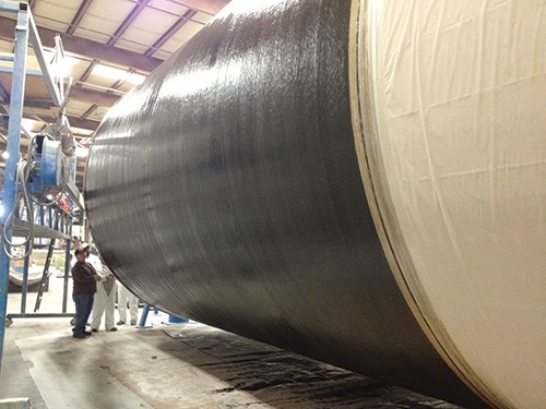
After veil placement, the fiberglass laminate was built up over the liner and veil on the rotating mandrel. Filament winding, in the axial and hoop directions (0°/90°), alternated with sprayup, between selected plies, of chopped Advantex fiberglass roving supplied by Owens Corning (Toledo, Ohio), wet out with Derakane 470-300 epoxy vinyl ester from Ashland Performance Materials (Columbus, Ohio).
Assembly integrity
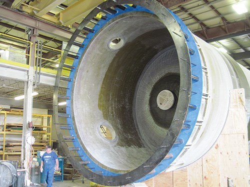
The central cylindrical shell, however, had to be fabricated differently than the top and bottom shells, explains Linnemann, because it was necessary to form the four ledges that would support scrubber trays in service. They had to be integral to the shell. Essentially, they were molded protrusions of the dual laminate on the interior of the vessel. One-piece construction was necessary — the design did not permit fastening of separately molded ledges because use of hardware in the interior could penetrate the liner. “It was a tricky part of the design, to ensure continuity of the laminate and the thermoplastic liner to form the ledges,” Linnemann notes.
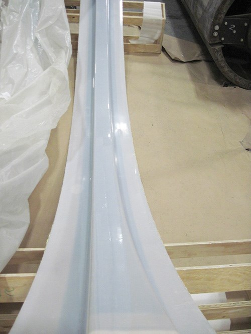
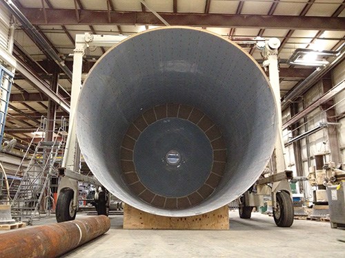
To facilitate ledge formation, RL Industries custom-designed and built another mandrel, ringed with four recesses approximately 4.5 inches/110 mm deep and 4.5 inches/110 mm wide, where the ledges were to be located. After placement and welding of the ETFE liner sheets over the majority of the mandrel, additional ETFE liner material was shaped offline in a separate, heated tool to create the ledge liners (see Step 5 and 6, p. 45). These were made in 90° arc segments, four for each ledge, which were then inserted into the mandrel recesses and flow fusion-welded together to form a continuous ring for each ledge. Workers manually welded the edges of these ledge liners to the liner sleeve on the mandrel to establish liner continuity. Then, the shell laminate was wound over the mandrel as described for the other shell sections, but also extended down into each recess, to form the integral, monolithic interior composite ledges.
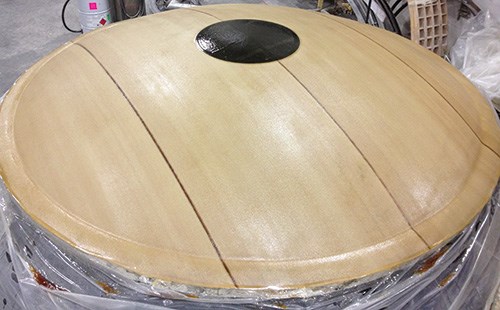
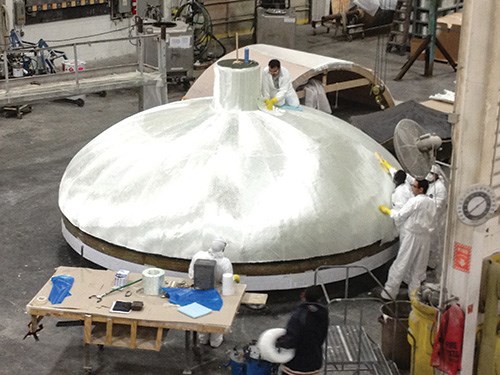
The two domed heads that form the vessel ends were fabricated in a separate process. ETFE liner material was laid out on a flat table and CNC-cut to part dimension on an ultrasonic machine made by American GFM (Chesapeake, Va.), with seams engineered to minimize their length and number. Pieces were butted together and flow fusion-welded. Each seamed disk was then placed in a female dish tool, sealed and vacuum-bagged and then heated to soften the plastic, while a vacuum was drawn in the tool to form the head liner. For head dome layup, the welded liner was placed over a hemispherical steel male mandrel (see Step 8, at left), followed by the 0.5-oz carbon veil and then dry woven fiberglass fabric supplied by Fiber Glass Industries Inc. (FGI, Amsterdam, N.Y.). Afterward, each head was bagged and infused with the same Ashland Derakane epoxy vinyl ester resin and allowed to cure at room temperature.
After cure, the heads were attached to the upper and lower shells on the winding mandrel. Workers then meticulously butted together, trimmed and hand-welded the exposed edges of the ETFE liners on the shell and domed heads, says Linnemann, ensuring that the conductive veil was also continuous across the seam. To join the overlying composite laminate, laminate plies were extended onto the head during the filament winding process.
Even trickier, says Linnemann, was the assembly of the shell sections to form the finished vessel. “It was a real challenge to line up 18-ft diameter sections with a knife-edge of liner and weld them together. We had to support 30,000 lb with custom fixtures to bring it all together.”
When all of the thermoplastic welds were complete, RL Industries had to confirm the continuity of liner conductivity via spark testing, which involves passing an AC spark tester over the entire interior vessel surface, with the tester set at 15 kV per millimeter of liner thickness. If the spark grounds to the conductive carbon veil, then that indicates a hole in the lining has been found and must be repaired.
After spark testing validated liner integrity, the joined shell sections were wet-laminated together. Anchor holes in the bottom supporting skirt section were subsequently drilled, using a full-scale steel bolt template: “The base ring holes were required for the client to attach the vessel to its foundation at the facility with anchor bolts. We shipped the bolt template with the vessel so they could correctly locate those bolts.”
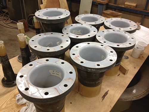
Fabrication also included the installation of fiberglass nozzles to feed gases and liquids into and out of the scrubber vessel. Each nozzle, with the largest measuring 30 inches/750 mm in diameter, was fabricated using a wet layup process. The ETFE lining in the nozzle flange and neck was formed and welded prior to the application of laminate to the embedded-fabric side. RL’s crew then trimmed the nozzle parts and cut bolt holes in the flanges on its high-pressure waterjet cutting system, which features a Flow International (Kent, Wash.) pump on a custom-built gantry with an in-house controller programmed in BobCAD (BobCAD-CAM, Clearwater, Fla.). As with other secondary joints, ample ETFE material was left exposed at the nozzle neck to enable welding of the nozzle liner to the vessel’s liner, explains Linnemann. “It requires a lot of skill to cut through the vessel wall without damaging the liner, then to trim and weld the liner of the nozzle to the interior liner and ensure liner continuity.”
Logistics on a large scale
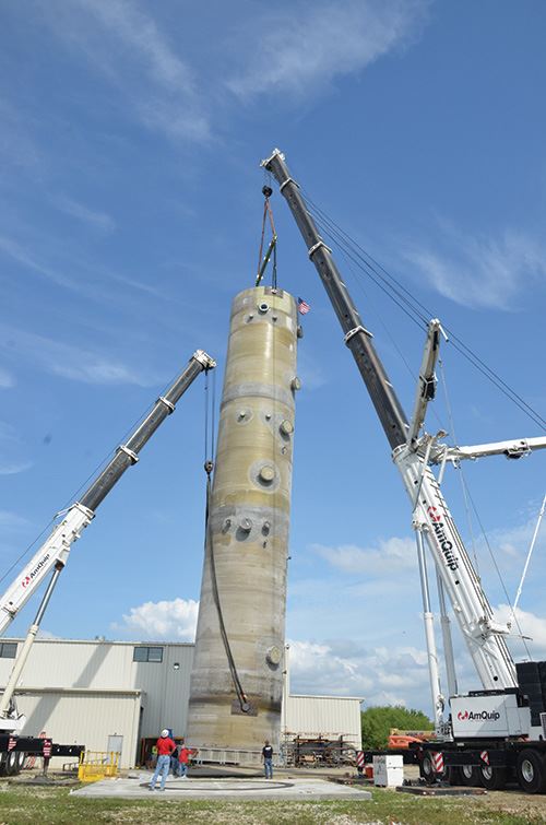
Client specifications required that the vessel undergo acoustic emission monitoring during the factory hydrostatic test, or hydrotest, to verify the completed vessel’s fitness for service. Linnemann explains that hydrotesting required, first, that the assembled vessel be in its as-installed vertical configuration. This was accomplished carefully with cranes under the client’s watchful eye. Second, the righted vessel had to be filled with water and then pressurized to 110 percent of its design service pressure of 14.5 psig (pound-force per square inch, gauge). Acoustic sensors were placed at customer-specified locations on the outside of the vessel to detect cracking sounds that would indicate flaws caused by excessive movement or flexing of the laminate during the test’s two-hour holding period. The vessel passed the test, with acoustic noise measurements well within acceptable limits.
Although the vessel was now complete and deemed fit for service, one of the more formidable challenges remained. RL Industries had to transport the assembled scrubber from Ohio to its final destination in the Middle East.
It was no mean feat. For the relatively short 75-mile over-the-road trip from RL’s facility to a shipping port on the Ohio River near Cincinnati alone, arrangements had to be made with local authorities before the scrubber design was even off the drawing board.
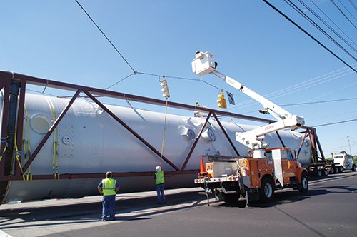
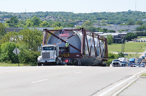
“The complex factory-to-river logistics took a year of planning with the Ohio Department of Transportation,” says Linnemann. For that phase of the trip, he recalls, “RL designed and fabricated a 60,000-lb steel transport frame to cradle the scrubber during trucking so that it was suspended directly over the pavement to minimize its shipping height.”
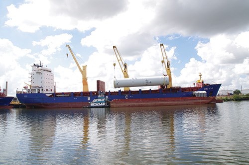
A fleet of electrical utility trucks was dispatched along with the tractor-trailer to lift power lines at each street intersection, so the huge load could pass safely underneath. When the vessel arrived at the Ohio river port, it was craned onto to a barge for the next leg of the trip west to the Mississippi River, then south through New Orleans into the Gulf of Mexico and west to the port of Houston, Texas. From there, it took about 10 weeks by ship to deliver the scrubber vessel to RL Industries’ client in the Middle East.
“This was not a simple, run-of-the-mill project,” Linnemann concludes with a bit of understatement. “Our best practices, and a lot of detailed planning and execution, ensured that the vessel will perform safely in critical service.”
Related Content
Renco USA brings Lego-style composite building system to construction
After more than a decade dedicated to R&D, evaluation and testing, the company has proven its MCFR building system in a Lakewood Village project in Florida.
Read MoreCirculinQ: Glass fiber, recycled plastic turn paving into climate solutions
Durable, modular paving system from recycled composite filters, collects, infiltrates stormwater to reduce flooding and recharge local aquifers.
Read MoreComposite SIPs for more affordable, efficient and sustainable buildings
LiteSIP panels and modules enable framing in days, cutting structural labor and total cost by up to 70% and 30%, respectively, while increasing energy efficiency and durability.
Read MoreSwedish parking garage to incorporate decommissioned wind blades
Architect Jonas Lloyd is working with Vattenfall to design the multistory building with a wind blade façade, targeting eco-friendly buildings and creative ways to remove blades from landfills.
Read MoreRead Next
Developing bonded composite repair for ships, offshore units
Bureau Veritas and industry partners issue guidelines and pave the way for certification via StrengthBond Offshore project.
Read MoreVIDEO: High-volume processing for fiberglass components
Cannon Ergos, a company specializing in high-ton presses and equipment for composites fabrication and plastics processing, displayed automotive and industrial components at CAMX 2024.
Read MoreAll-recycled, needle-punched nonwoven CFRP slashes carbon footprint of Formula 2 seat
Dallara and Tenowo collaborate to produce a race-ready Formula 2 seat using recycled carbon fiber, reducing CO2 emissions by 97.5% compared to virgin materials.
Read More

