FACC AG: Aerocomposites Powerhouse
This pragmatic Austria-based innovator is pursuing lofty goals in an aerocomposites future full of opportunity.
When it received Frost & Sullivan’s Global Market Share Leadership Award in 2012, FACC AG (Ried im Innkreis, Austria) already had a 30-year history in composites and had become a Tier 1 supplier to Airbus, Boeing, Bombardier, Dassault and Embraer. Yet it remains relatively unknown in the composites industry.
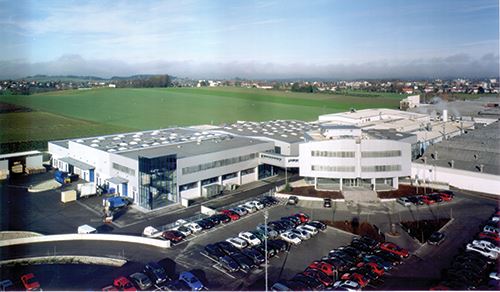
This hardly seems possible for a company that holds contracts for parts on every major commercial airframe now in production. FACC employs more than 3,000 people (more than 700 are engineers) and maintains four fabrication facilities, totaling 60,300m2/649,000 ft2, in Austria alone. But it also has forged joint ventures in Russia, China and Abu Dhabi, U.A.E., and has customer support/engineering operations in China, Germany, India, Russia, Canada and the U.S.
The company has focused on three product portfolios: Interiors, Aerostructures and Engines & Nacelles. Considering innovation one of its core capabilities — e.g., the now-standard door hinge with integrated damper for interior stowbins and the industry’s first composite wingbox components produced in a one-shot, out-of-autoclave (OOA) process — FACC is poised to expand into primary structures and recently guided HPC through several of its Austrian facilities, offering the following glimpse into its global operation. (Take a walk through FACC history by clicking on “FACC timeline: Engineer-centric evolution,” under "Editor's Picks," at top right.)
Emphasis on innovation
HPC was accompanied by CEO Walter Stephan and aerostructures product development director Hermann Filsegger. Asked to account for FACC’s obvious success, they were quick to point out the company’s focus on finding ways to cut weight, reduce fasteners and part count, simplify installation and reduce costs.
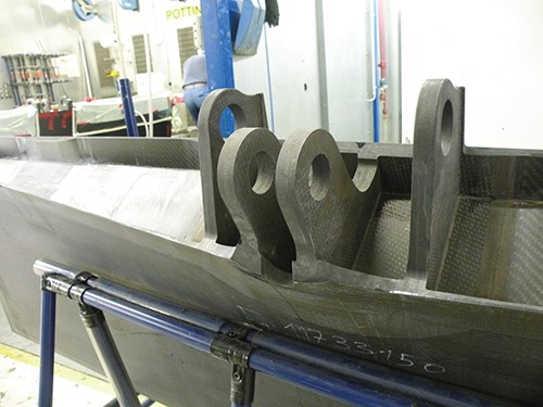
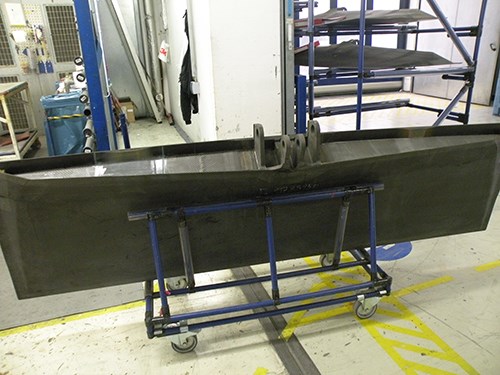
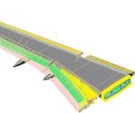
A case in point involves spoilers for the Airbus A330/A340, previously assembled from several precured carbon fiber-reinforced polymer (CFRP) parts bonded to an aluminum main fitting. However, the difference in coefficient of thermal expansion (CTE) between the CFRP and aluminum was an issue. “We saved 15 percent weight vs. the original design by using RTM [resin transfer molding] and CFRP,” said Filsegger. “We had no more CTE issues nor need to purchase expensive forged metal fittings.” Since then, FACC has developed the design further for the A350 XWB (see Fig. 1 and Fig. 2, at left). Filsegger noted, “The RTM fitting has flown on the A330 for years without any problem.”
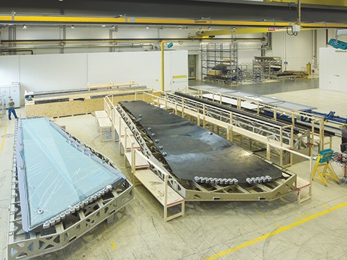
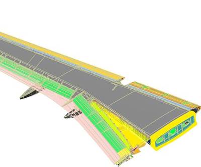
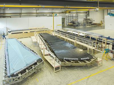
The resin is Cytec (Woodland Park, N.J.) 977-20 toughened epoxy. And it was Cytec, in fact, which suggested FACC involvement in the Irkut (Moscow, Russia) MS-21 wingbox program (for more on this program click on “Resin-infused MS-21 Wings and wongbox,” under "Editor's Picks"). “The customers knew they wanted to proceed with an OOA composite concept for the wing but were looking for a partner with expertise in the technology,” Filsegger recalled, contending that FACC’s tooling concept was “smarter” than its competitors’, both for the infusion process and final assembly. (FACC’s infusion process — a proprietary and patented system — is described in the sidebar “FACC: Aerospace infusion pioneer.” See it at the end of this article or click on its title under "Editor's Picks.") Why? “Because we calculated the thermal expansion and laminate warpages so that the resulting parts are true to dimension,” he explained, adding, “Not just expansion and shrinkage, which is expected, but more importantly, we could manage the remaining springback in final assembly.”
This, on a 1-inch/25.4-mm thick spar at the root, would make it impossible to bend the part into its necessary shape. “And even if you did,” said Filsegger, “you would introduce an uncontrolled preload on the fasteners, which is not permissible. Our tools could handle springback effects easily, allowing the skin to fit perfectly to the ribs and spars. And it was right the first time.” According to Filsegger and Stephan, this was possible because FACC had considered all of the risks during infusion and final assembly from the start. “For us, it was a standard technical risk assessment, but it is key to developing innovations so that you can deliver what is promised.”
When asked if FACC foresees building OOA wings in the future, Stephan explained that OEMs will likely retain (and in Boeing’s case reclaim) control of the wing. So what future primary structure is the target? “We have developed our expertise so that OOA vertical or horizontal stabilizers will be readily achievable.”
Winglets, spoilers, bypass ducts
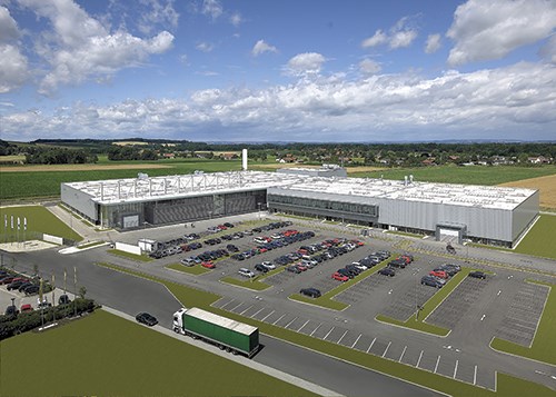
The tour commenced in Plant 1, which houses FACC’s corporate headquarters as well as production of aerostructures and some engine and nacelle components. Tour highlights in the 21,000m2/226,000-ft2 facility included winglet, spoiler and engine bypass duct operations.
A global leader in the development and production of winglets, FACC delivered its first set of Aviation Partners Boeing’s (APB, Seattle, Wash.) trademarked Blended Winglets for the Boeing 737 Next Generation (i.e., -600/-700/-800/-900 series) in 2002. It then worked with APB to retrofit them to Boeing 757 aircraft. In 2010, FACC delivered the 3,000th shipset of Blended Winglets and was named single-source supplier for the product lifetime.
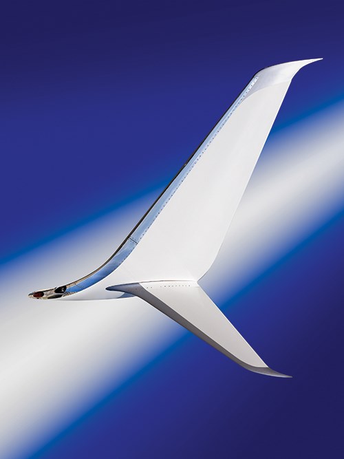
It collaborated again on APB’s next design, the Split Scimitar Winglet (see Fig. 4), performing stress analysis, manufacturing development and production tool design and fabrication. The name describes use of both a split winglet design and high-performance scimitar-shaped tips, which, combined, cut aircraft fuel consumption by about 2 percent. FACC prototyped the winglets in only three months.
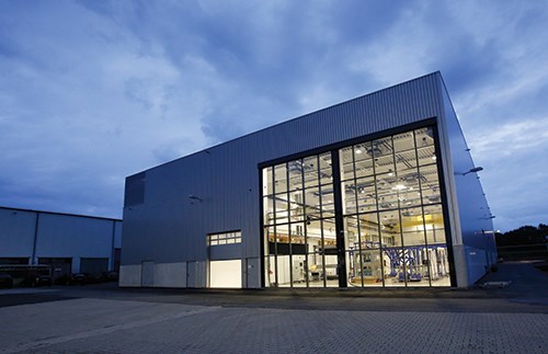
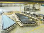
In 2013, FACC worked with Airbus to develop new winglets for the A350 XWB, which measure 2.3m/7.5-ft wide at the base and 2m/7-ft high. FACC was responsible for the development, qualification, production tooling design and fabrication, as well as testing, series production and assembly of the individual components into a ready-to-install system for delivery to the Airbus final assembly line (FAL) in Toulouse, France. This program was the first in which tests on full-scale parts of this size — wingtips with attached winglets are 6m/20-ft long — were carried out at FACC’s Composite Lab and Test Center (see Fig. 4). The complete winglet system was subjected to static and dynamic testing for resilience, fatigue and endurance, up to mechanical failure, and was in the final stages of completion during HPC’s tour.
Elsewhere in Plant 1, myriad automated cutting machines raced through meters of carbon fabric and prepreg in several large glass-encased kitting rooms. Behind these were massive cleanrooms where skins, stiffeners and other structures are hand-layed onto arrays of production tools. These tools are loaded into various autoclaves and ovens in the facility, after which parts are transferred to dedicated assembly areas.
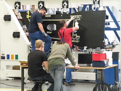
Walking through the area for Split Scimitar Winglet assembly, 8 to 10 fixtures supported winglets in various stages of completion. The structure featured CFRP skins with bolted stringers and numerous brackets for lights and glazing to be attached later (see Fig. 5). FACC also paints the winglets with each airline’s livery in an adjoining paintshop, complete with multiple spray booths and a large open area reserved for final detailing.
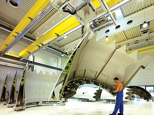
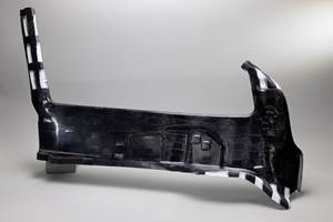
Moving on through one of the spoiler fabrication areas, racks of completed spoilers shared space with parts in progress on mobile fixtures. Filsegger pointed out the RTM fitting for the A350 XWB spoiler — a massive and, visually, impeccable layup of carbon composite, with no detectable voids or distortion.
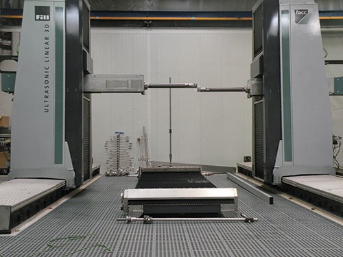
An adjoining area featured large CNC-machining bays as well as automated nondestructive testing (NDT) cells, including two new machines supplied by local machinery company Fill (Gurten, Austria). One was a high-speed, 10-axis, 3-D linear ultrasound system capable of through-transmission and pulse echo interrogation. Designed for high throughput (linear speed up to 1.7 m/s) and high accuracy (±0.2 mm), two electronically coupled, numerically controlled modules move the inspection heads along a 3-D path generated via interface with standard CAD systems. The second system uses a 7-axis robotic arm to perform pulse-echo ultrasound testing with the same basic speed and accuracy of 3-D inspection. As FACC series production ramps up for a program, Filsegger explained that every part is inspected until statistical quality performance is established over a specified number of parts. After that, defined periodic sampling is considered sufficient.
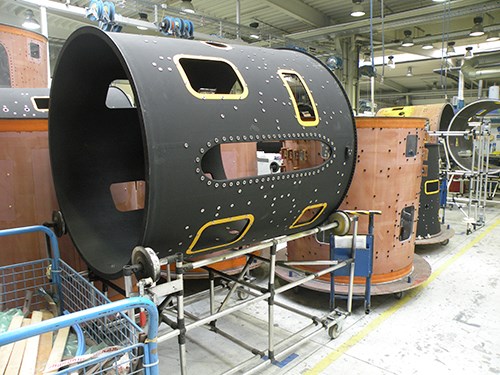
Before leaving Plant 1, HPC passed through one of the larger open areas within the building, populated by a number of barrel-shaped structures with various-shaped cutouts. Another FACC area of expertise, these were lightweight, sound-absorbing composite outer bypass ducts, which channel the outer (bypass) airflow around the hot core in turbofan engines. FACC worked with Pratt & Whitney to develop the latter’s first composite bypass duct in 2002, and has produced more than 1,000 similar parts for Rolls Royce’s (London, U.K.) BR700 family of engines since 2001. The Pratt & Whitney structure uses a sandwich construction with carbon fiber/epoxy skins that feature a 2x2 twill prepreg and aluminum honeycomb core. FACC also developed a sound attenuation treatment for the duct’s inner skin. In 2013, after only 12 months of development, FACC delivered several variations of a new design for the PurePower PW800 engine aimed at long-range business jets, regional jets and single-aisle jetliners and looks forward to beginning serial production soon.
Interiors, now and tomorrow
The tour’s next leg took HPC to Plants 2 and 3, 10 km/6.2 miles away in Ort im Innkreis. Plant 2 houses interiors production. “There are only three companies who can design, develop and supply a complete aircraft interior,” Stephan pointed out. “Diehl [Laupheim, Germany], Boeing Interiors Responsibility Center [North Charleston, S.C., and Everett, Wash.] and us. We make and supply all of the components needed, from cargo to cabin.” FACC now owns a 20-plus percent share of the commercial aircraft cabin market. Filsegger credited that to FACC’s innovative approach to interiors, which dates back to the first MD-95. He recounted an example, “The line of stowage bins, sidewalls and ceiling panels inside the finished cabin had to be precisely level.” However, he described the plane’s aluminum fuselage sections as “flexible tubes” to which composite interiors were attached using myriad adjustable brackets. Thus, interior unit alignment required painstaking adjustment of hundreds of hard-to-reach threaded tie rods. “We developed a laser-aligned installation, which located a highly effective new type of attachment, independent of the incongruities in the fuselage barrels, which was very fast and efficient.”
FACC also pioneered the now-standard hinge used on practically every fixed-shelf stowage bin (overhead compartment) door. “It used to be that this hinge had an air- or spring-loaded actuator that extended back into the bin, but made the corners unusable space,” Filsegger recalled. FACC’s smaller, more reliable hinge incorporates the actuator into the hingeline, opening up that space.
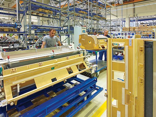
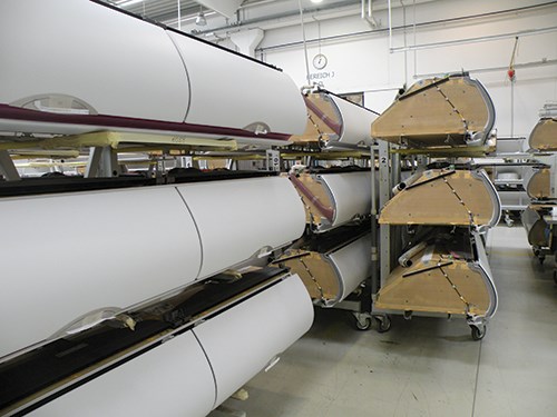
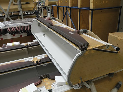
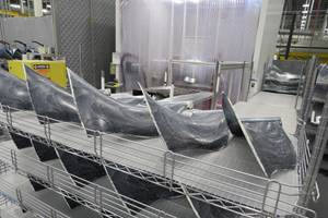
Plant 2’s landscape revealed rack after rack of completed bins and numerous fabrication and assembly areas, each devoted to a different aircraft’s components. The stowbins are all made from flat honeycomb-cored panel stock and curved cored doors, with attachment points prepotted to accommodate hardware. For many of the units, oddly shaped composite duct modules — most made from lightweight glass fabric and phenolic resin — are also prefabricated and then attached during assembly (see Fig. 6). After mechanisms and trim are added, finished bins are strapped into specialized containers and shipped to Diehl for rigging of electrical and other systems. FACC continues to increase unitization of the parts it ships. One example is a composite “plug and play” module for the A350 XWB smoke detection panel, designed In cooperation with Siemens Process Industries and Drives (Buc Cedex, France), which reduces part mass and makes it easier and more economical to install than conventional panels.
Although the materials and processes used in stowbins have been standard for decades, Stephan says FACC always looks for new options, but he admits, “crushed core is hard to beat because it is very robust … and it’s easy to push out part after part with consistent quality and not a lot of quality control intervention. It is also cheap.” When asked if thermoplastic composites hold promise, Stephan was cautious, “The problem is that in order to get the fire, smoke and toxicity [FST] performance, you are forced into materials that are 10 times the cost of current phenolic and honeycomb.” Nor does he think thermoplastic composites could increase throughput. “We are already press-forming the phenolic parts with a cycle time as low as 30 minutes for large baggage bin doors,” he says. “There is also a limit to the weight savings you can achieve on a sidewall, for example, because noise transmission is governed by mass.”
Plant 2 also incorporates a very large core machining area, with two new CNC milling machines used only for honeycomb supplied by Reichenbacher Hamuel (Dörfles-Esbach, Germany) with clamping systems by Inteccs (Dortmund, Germany). Filsegger explained that it is more economical for FACC to mill honeycomb in-house and, as we passed a vast landscape of machined core, he pointed out, “All of this is only for today’s production.”
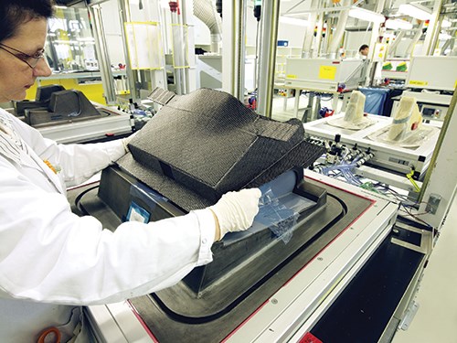
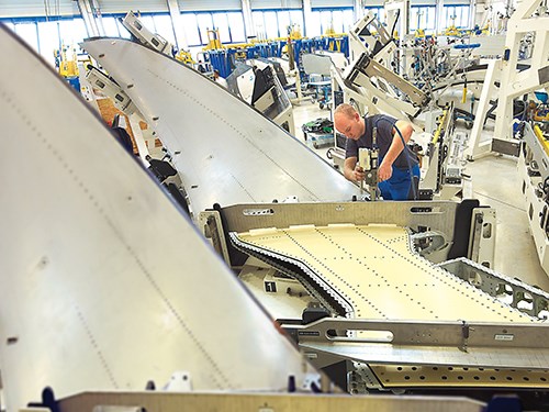
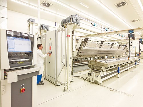
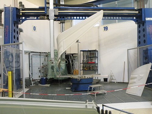
In Plant 3, a wide variety of flaps, fairings and flight control surfaces are manufactured. Here also, efficiencies from automated tape laying (ATL) and hot drape forming are exploited. The latter applies heat and pressure to flat ATL preforms using a core and flexible forming pad to produce three-dimensional shapes (see Fig. 7). One example is ongoing A321 flap production, which uses a cutting-edge automated workcell custom-engineered by Fill.
Large engine parts
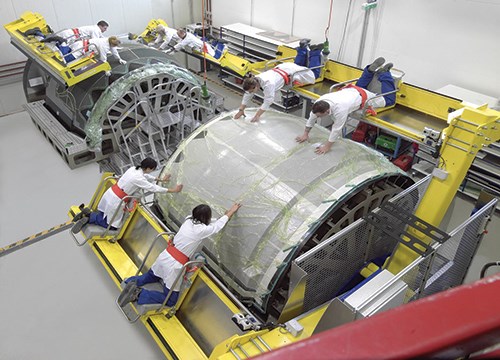
In Plant 4, another 21,000m2 facility, FACC manufactures a wide array of engine and nacelle components. Filsegger highlighted FACC’s large composite translating sleeves, critical components in the cascade thrust reverser systems used in today’s commercial jet engines. Sleeve cowls are hand layed (see Fig. 8) in large glass-fronted cleanrooms, the complex layups facilitated by laser projection systems (SL Laser, Traunreut, Germany).
For the Boeing 787, FACC worked with customer UTC Aerospace Systems (UTAS, Charlotte, N.C., previously Good-rich Aerostructures) to develop, engineer and qualify the first sleeve to use a double-degree acoustic surface and undulated (chevron) engine nozzle design, both achieving significant noise reduction. Working again with UTAS, FACC also developed a weight-optimized design for the Airbus A350 XWB. Both programs are now in production.
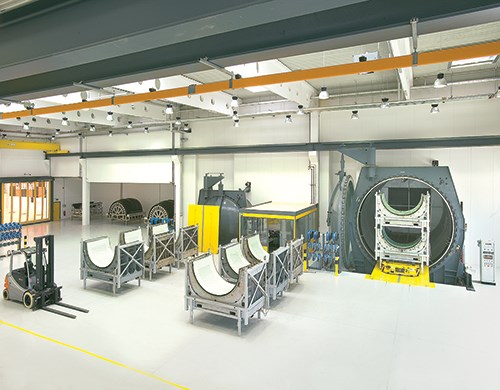
Plant 4 also houses two large autoclaves (see Fig. 9) built by Maschinenbau Scholz GmbH & Co. KG (Coesfeld, Germany). One is 12m/40-ft long by 4.5m/13 ft diameter and the other is 12m long by 6m/20 ft diameter. Each is capable of 250°C/482°F and able to accommodate the sleeve cowls and other massive parts.
After cure, the various sleeve components are assembled, each sleeve is painted and then proceeds through quality assurance (QA). Plant 4 also accommodates an 8 by 4 by 2m (26- by 13- by 7-ft) 5-axis CNC milling machine and multiple laser coordinate measurement machines and ultrasonic inspection units that facilitate QA.
Firmly on the edge
Now a leading Tier 1 aerostructures supplier, FACC’s visibility is increasing. The RTM composite annulus filler it developed with Rolls Royce as part of the CleanSky Initiative was recognized with a 2014 JEC Innovation Award. FACC also is in active pursuit of technology that, if successful, will ensure FACC a future share in the spotlight: It’s R&D group’s desire to cut next-gen jet engine fan blade weight by 40 percent vs. metal predecessors is just one of many examples.
Looking into FACC’s future, Stephan claimed that the company’s financial targets — including $1 billion USD (€799 million) in total revenue by 2016 — are readily achievable, given the aerocomposites market’s 5 percent annual growth rate. Although he acknowledges that “China and Russia are more long-term investments,” FACC is nonetheless actively pursing growth in the East and will soon assume a 24 percent share in the KAPO-Kompozit facility (Kazan, Tatarstan). This 33,000m2/355,000-ft2 facility will not only produce flaps, elevators, rudder and fairings for Superjet International’s (Venice, Italy) SSJ-100, but autoclaved prepreg components for Airbus and Boeing aircraft as well. “We are qualifying the Kazan plant now as a new FACC site,” says Stephan. “We have already done this with the facility in Abu Dhabi where we have partnered with Mubadala, and are proceeding, likewise, in China.”
For some, the risk of expansion into new markets is an obstacle. For FACC, it’s an opportunity enabled by its OEM-recognized emphasis on engineering and program management. Stephan contends, “The key to all of our locations is that we ... can not only control the production processes but also protect our customers’ intellectual property.” He adds that despite its diverse operations and large number of different part programs, “our additional strength is that we have always been solely focused on composites.”
Related Content
Highly tunable, woven lattice reinforcements target automotive structures
CAMX 2023: Startup Weav3D will be demonstrating its two collaborative automotive demonstrator parts and present two conference papers.
Read MorePlant tour: Albany Engineered Composites, Rochester, N.H., U.S.
Efficient, high-quality, well-controlled composites manufacturing at volume is the mantra for this 3D weaving specialist.
Read More3D-woven composites find success in aerospace, space
CAMX 2024: Bally Ribbon Mills experts are displaying the company’s various joints, thermal protection system (TPS) technologies and other 3D woven composites for mission-critical applications.
Read MoreComposite resins price change report
CW’s running summary of resin price change announcements from major material suppliers that serve the composites manufacturing industry.
Read MoreRead Next
Resin-infused MS-21 wings and wingbox
Moscow-based aeromanufacturer uses out-of-autoclave composites in attempt to leapfrog Airbus and Boeing with wider, lighter, more efficient single-aisle airliner.
Read MoreFACC: Aerospace infusion pioneer
Although it’s “new” to aerospace, liquid resin infusion has been the focus of R&D at FACC (Ried im Innkreis) since 2001. “The issue,” said FACC’s aerostructures product development director Hermann Filsegger, “is in getting 100 percent wetout with no voids in a large part with this much complexity.” That’s not, by any means, an easy task.
Read More

