
Fastener shear test methods
Dr. Donald Adams (Wyoming Test Fixtures, Salt Lake City, Utah) appraises existing methods for testing the performance of fasteners loaded in transverse shear.
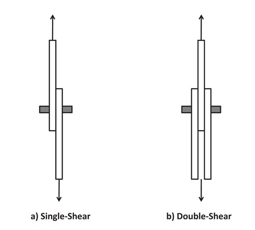
Fig. 1: Fastener loaded in single-shear vs. double-shear. Source: Don Adams
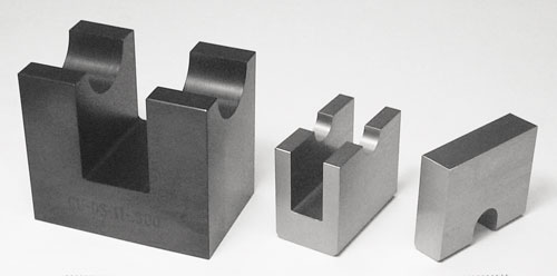
Fig. 2: Disassembled fastener double-shear test fixture (NASM 1312-13). Source: Don Adams
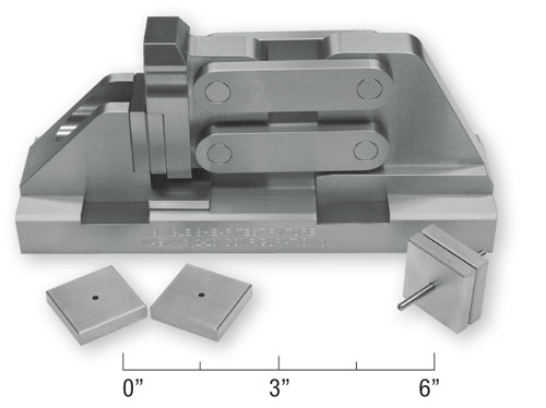
Fig 3: Single-shear test fixture (NASM 1312-20). Source: Don Adams
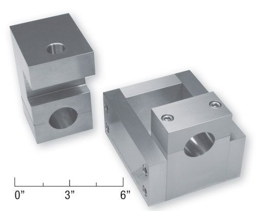
Fig. 4: Example of a nonstandard single-shear test fixture. Source: Don Adams
Share
Read Next

Mechanical fasteners, such as screws, bolts, pins and rivets, have been used for hundreds of years to assemble wood and metal structures. As composites have replaced other materials in structural applications, the use of mechanical fastening systems of various types has continued, and occasionally these systems even employ fasteners made from composite materials. Although one goal of the composite materials community is to use fewer fasteners and rely more on adhesive bonding when assembling components, fasteners remain in widespread use and, therefore, require testing.
In service, the typical fastener is loaded primarily in one of two ways: axial tension or transverse shear. Shear loading is much more common. Axial tensile testing of fasteners is relatively straightforward and requires minimal specialized fixturing. This is not true for shear testing; therefore, considerable development work has been conducted over the years. Depending on the design of the joint, the shear loading is single or double shear, as indicated in Fig. 1. Obviously, the fastener can carry twice as much load if it is subjected to double shear. Also, double shear results in symmetrical loading, which minimizes bending effects in both the fastener and the structure. But a structural design may not permit this configuration.


In double-shear testing, the fixture is, by far, most commonly some version of that shown in Fig. 2. This particular fixture conforms to NASM Standard 1312-131, often (and properly) still referred to as MIL-STD-1312-13. No scale is indicated in the photograph because each fixture is sized to fit a specific fastener diameter. The diameter of the fastener can range from a few millimeters to several centimeters. Therefore, some fixtures for testing large-diameter fasteners are relatively massive — and expensive.
The NASM design in Fig. 2 is a three-piece configuration consisting of a base, an anvil and a blade. Although it provides additional stability, it is questionable what other function the base performs, so it could probably be eliminated. In fact, it is missing in some fixture designs (e.g., the fixture in Boeing Corp. Specification D2-28602).
In the NASM Standard 1312-13 design, the fastener is placed across the supporting anvil and sheared into three pieces by a compressive force applied to the blade. The relative thicknesses of the anvil supports and the blade, as well as the tolerances of various other critical dimensions, are defined in the standard. This fixture has existed for many years and performs well. One emerging problem, however, is that metallic fasteners, particularly some of those now used in the aerospace industry, are being made of progressively stronger materials. It is increasingly difficult to find materials from which to fabricate an anvil and blade that are stronger and tougher than the fastener material. Currently, fixtures are most commonly made from high-hardness tool steel.
Less frequently used are double-shear designs in which the fastener passes through holes in the anvil and blade instead of resting in semicircular cutouts. This fixture configuration is specified in ASTM Standard B 7693, sometimes referred to as the Amsler Shear Fixture, and in British Standard BS EN 28749 (ISO 8749).4
Although single-shear testing of joints is frequently conducted, single-shear testing of the fastener itself is less common. In one method, NASM Standard 1312-205, three single-shear test fixtures are described in detail. All three use the same shear plates, but two use a large number of ball bearings to minimize friction between the moving parts. The third fixture is more practical, using a parallel-bars linkage to load the closely spaced shear plates without allowing them to come into contact with each other. This fixture is shown in Fig. 3. There are no sliding surfaces, only pivot rotations, thus minimizing frictional effects. In all three of the fixture designs, the fastener is inserted in the center hole of a pair of shear plates, as indicated in Fig. 3. The overall dimensions of the shear plates are held constant so they fit in the fixture. The center holes vary to accommodate the specific fastener. Hole diameters are held very close to the specific fastener diameters.
In addition to standardized designs, such as that shown in Fig. 3, there are a number of other single-shear fixture designs that have been developed for specific applications. A representative example is shown in Fig. 4. In this case, the fastener specimen is clamped in the base after insertion into the close-fitting hole in the loading head. The box-shaped opening in the base constrains the loading head to keep the shearing edges in close proximity. Although the fixture details differ, the basic test principle — application of a single-shear load to the fastener — is in operation. This is true of most other ad hoc fixtures as well.
At the present time, the NASM Standard 1312-13 double-shear fixture shown in Fig. 2 is probably the best available shear fixture for testing fasteners.
Editor's Note: To read Dr. Adams’ previous discussions of fastener-related testing of composites, see the articles listed under “Editor's Picks").
Wyoming Test Fixtures Inc.
References
1NASM 1312-13, “Method 13-Double Shear,” National Aerospace Standard, Aerospace Industries Association of America Inc. (Arlington, Va.), 1997. This standard supersedes MIL-STD-1312-13A, but the test method designation remains MIL-STD-1312-13.
2Boeing Corp. Specification D2-2860, The Boeing Co. (Seattle, Wash).
3ASTM Standard B 769, “Shear Testing of Aluminum Alloys,” ASTM International (W. Conshohocken, Pa.), 2008 (originally published 1987).
4British Standard BS EN 28749 (ISO 8749:1986), “Pins and Grooved Pins — Shear Test,” approved by CEN Technical Committee 185, 1992.
5NASM 1312-20, “Method 20 — Single Shear, National Aerospace Standard,” Aerospace Industries Association of America Inc. (Arlington, Va.), 1997. This standard supersedes MIL-STD-1312-20, but the test method designation remains MIL-STD-1312-20.


Related Content

ASCEND program update: Designing next-gen, high-rate auto and aerospace composites
GKN Aerospace, McLaren Automotive and U.K.-based partners share goals and progress aiming at high-rate, Industry 4.0-enabled, sustainable materials and processes.
Read MoreComposites manufacturing for general aviation aircraft
General aviation, certified and experimental, has increasingly embraced composites over the decades, a path further driven by leveraged innovation in materials and processes and the evolving AAM market.
Read More
Plant tour: Spirit AeroSystems, Belfast, Northern Ireland, U.K.
Purpose-built facility employs resin transfer infusion (RTI) and assembly technology to manufacture today’s composite A220 wings, and prepares for future new programs and production ramp-ups.
Read More
A new era for ceramic matrix composites
CMC is expanding, with new fiber production in Europe, faster processes and higher temperature materials enabling applications for industry, hypersonics and New Space.
Read MoreRead Next

Testing Tech: Multiple-fastener, single-shear laminate bearing strength testing
Dr. Don Adams (Wyoming Test Fixtures Inc., Salt Lake City, Utah) follows up his HPC January 2008 discussion of double-shear testing of a single fastener while advice about testing multiple fasteners under single-shear loading conditions.
Read More
Single-fastener, double-shear laminate bearing strength by tensile testing
Dr. Don Adams (Wyoming Test Fixtures Inc., Salt Lake City, Utah) discusses a laminate bearing strength test using double-shear loading of a single fastener.
Read More
All-recycled, needle-punched nonwoven CFRP slashes carbon footprint of Formula 2 seat
Dallara and Tenowo collaborate to produce a race-ready Formula 2 seat using recycled carbon fiber, reducing CO2 emissions by 97.5% compared to virgin materials.
Read More