Single-fastener, double-shear laminate bearing strength by tensile testing
Dr. Don Adams (Wyoming Test Fixtures Inc., Salt Lake City, Utah) discusses a laminate bearing strength test using double-shear loading of a single fastener.
As composite materials are used more extensively in structural applications, some test methods that once were considered very specialized and, therefore, not widely used, have become more significant. Methods for testing laminate bearing strength are one example.
Although polymer-matrix composites lend themselves to assembly by adhesive bonding, some joints require disassembly to permit interior access, thus allowing for replacement in the event of damage and/or ease of transport. In these cases, joints are fastened mechanically.
Mechanically fastened joints can be complex, with multiple fasteners arranged in a pattern such that the individual fasteners share the applied loading in a prescribed way. Determining how much of the applied loading bypasses a given fastener to be carried by adjacent fasteners can be a complex process that must be addressed analytically and, perhaps, verified experimentally. Such investigations depend, however, on accurate data about the response of a single fastener in bearing contact with the laminate. The need for these data motivates much of the current use of laminate bearing strength test methods.
In a typical joint, the fastener, most commonly a bolt, bears against one side of the hole in the laminate. While the bolt itself might fail, perhaps by bending, failure of the laminate in the region of the hole is usually of greater concern. Obviously, a direct bearing (crushing) failure of the laminate is one failure mode. However, if there is insufficient distance between the hole and the end of the laminate, a shear-out might occur first. If the width of the laminate is insufficient, a net tensile failure might occur across the hole. These and other failures, including fastener failures, are likely.
The joint might consist of two plates fastened together, subjecting the fastener to single shear, or a single plate might be sandwiched between two plates, putting the fastener in double shear. The lack of symmetry in single shear subjects the fastener and laminates to bending moments, significant by themselves and because the bearing force on the laminates will not be uniform across the thickness. Double shear results in symmetrical loading, which eliminates the concern about bending. The type of test that should be used depends on whether the joint will be single- or double-shear. I will focus here on methods for testing in double shear.
Finally, the applied loading on the joint specimen can be tension or compression, again as best simulates the service condition. Note that the failure mode can be totally different. While bearing failures can occur under both types of loading, obviously shear-out or net tension failures do not occur under compressive loading. However, local plate buckling can occur in the fastener region. Here, we will focus on tensile loading.
Double shear of a single fastener, using one test laminate sandwiched between two fixture plates and loaded in tension, is the most commonly conducted of the laminate bearing tests. The fixture plates and fastener materials must have strength sufficient to guarantee that the failure occurs in the composite laminate test specimen. Typically high-strength steel is selected. To minimize bending of the fastener, it is desirable to have the two fixture plates in direct contact with the specimen. In fact, if a threaded fastener is used, the test procedure usually will specify that a light fastener torque be applied.
At present, there are in common use three standards with accompanying test fixtures that fit this description. All three specify a nominal 0.25-inch diameter loading pin, although ASTM D 953 also standardizes a 0.125-inch diameter pin test.
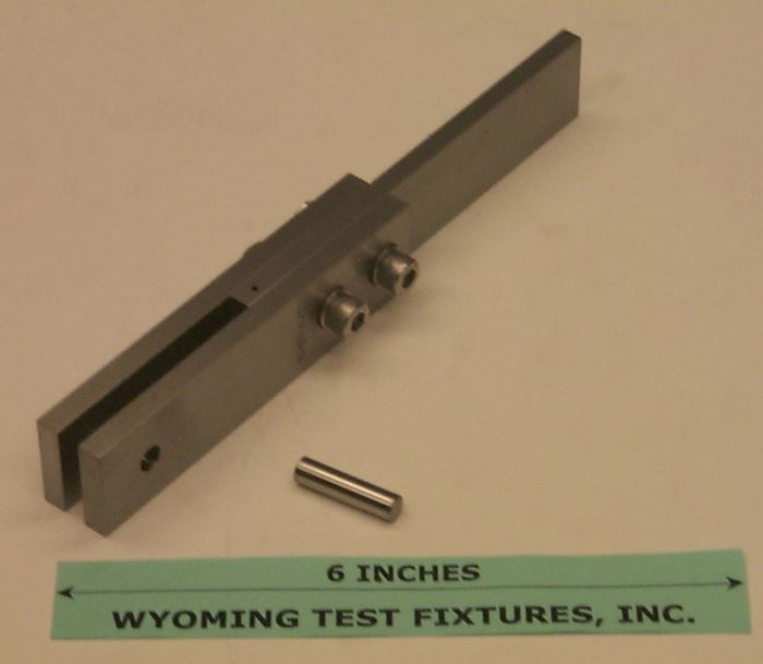
ASTM D 953 is the oldest of the three standards, having been developed originally for plastics and first published in 1948.1 It is similar to ASTM E 238 for metals, although the latter was not published until 1964.2 (For once, the plastics/composites standard preceded the metals standard.) The fixture is shown in Fig. 1. It consists of three steel plates bolted together. The smooth pin (the fastener) secures the drilled composite laminate in place between the two side plates. When the laminate is pinned, the upper end of the fixture and the lower end of the laminate are gripped in tensile wedge grips and loaded to failure. Note that there is no provision for adjustment of the fixture to accommodate variations in specimen thickness. Shims must be used, either between the three plates if the specimen is too thick, or between the specimen and the side plates if the specimen is too thin.
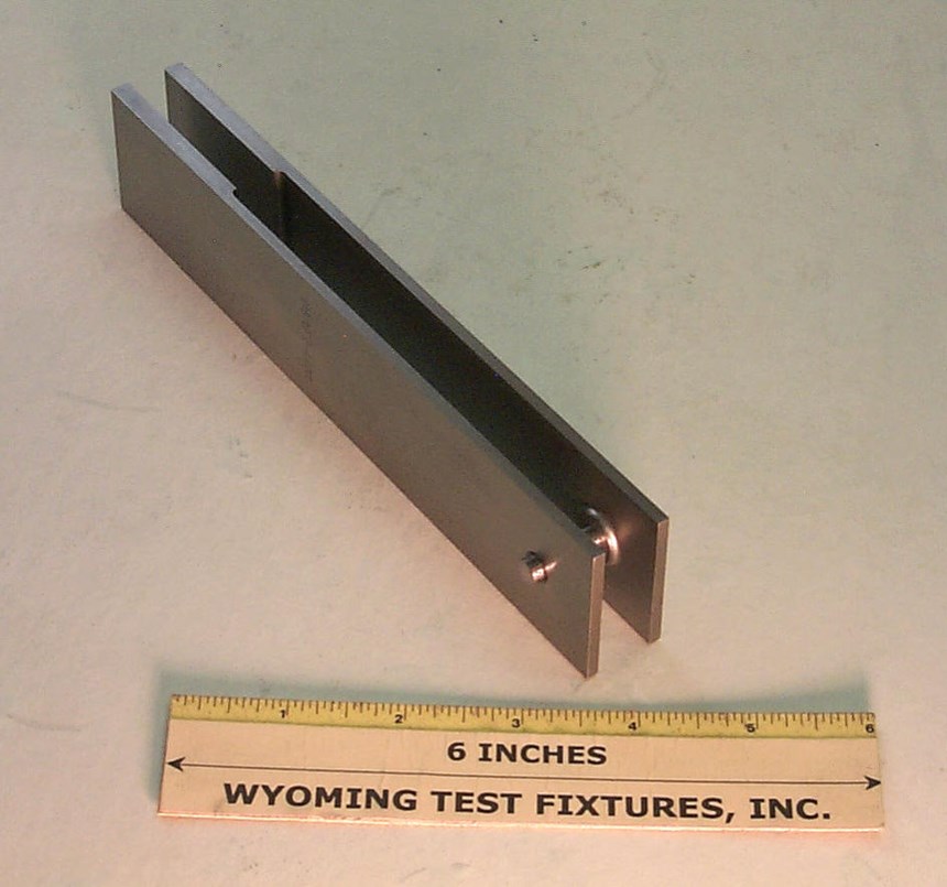
ASTM D 59613, first published in 1996, includes Procedure A, which suggests the fixture shown in Fig. 2. This simple fixture consists of identical halves. A spacer plate of the same thickness as the test specimen is used to maintain the spacing. Another piece of the test laminate is a logical choice. Either a pin or a threaded fastener is used to attach the specimen to the fixture. Circular bosses on the inner surfaces of the fixture halves ensure that only a well-defined area of the fixture is in contact with the specimen if a torqued fastener is used.
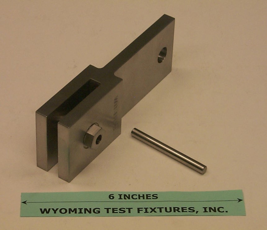
The third test method and associated fixture are commonly referred to as SACMA SRM 9-89.4 Interestingly, even though formal copies of this SACMA Recommended Method (SRM) were in circulation in the late 1980s and a separator sheet was provided in the original SRM three-ring binder, the document itself never appeared in the binder. An unrelated test method eventually used the SRM 9 designation. In 1994, Composite Materials Characterization Inc. (CMC)5, a consortium of companies, adopted the same test fixture as its bolt-bearing screening test method, referencing the SRM-9 document. Because both the SACMA and CMC organizations are now defunct, the SACMA fixture is orphaned. This is unfortunate because the fixture has several virtues. As indicated in Fig. 3, the body of the fixture is one piece, making it rigid and easy to handle, and its upper end can be gripped in a tensile wedge grip or pinned to a clevis in the crosshead of a testing machine. Bushings with internal sleeves thread into the body from each side. These bushings can be tightened against the laminate specimen with whatever force is desired, while automatically accommodating variations in thickness from specimen to specimen, eliminating the need for shims. The specimen is loaded in bearing by a smooth, hardened pin.
Although the SACMA fixture has a slightly more complex geometry and is, therefore, a little more expensive to fabricate, it is by far the easiest to use. For that reason, I recommend its use. Perhaps ASTM will eventually add this test fixture to its ASTM D 5961 standard.
References
1ASTM D 953-02, “Test Method for Bearing Strength of Plastics,” ASTM International (W. Conshohocken, Pa.), 2002.
2ASTM E 238-84 (2002), “Test Method for Pin-Type Bearing Test of Metallic Materials,” ASTM International (W. Conshohocken, Pa.), 2002.
3ASTM D 5961-05, “Test Method for Bearing Response of Polymer Matrix Composite Laminates,” ASTM International (W. Conshohocken, Pa.), 2005.
4SACMA SRM 9-89, “SACMA Recommended Test Method for Bearing Strength Properties of Oriented Fiber-Resin Composites,” Suppliers of Advanced Composite Materials Assn. (Washington, D.C.) 1989 (SACMA disbanded, June 2000).
5CMC Screening Method P6-7, “Bolt Bearing Strength Test,” Composite Materials Characterization Inc. (Folsom, Calif.), 1994.
Related Content
3D-printed CFRP tools for serial production of composite landing flaps
GKN Aerospace Munich and CEAD develop printed tooling with short and continuous fiber that reduces cost and increases sustainability for composites production.
Read MoreCarbon fiber, bionic design achieve peak performance in race-ready production vehicle
Porsche worked with Action Composites to design and manufacture an innovative carbon fiber safety cage option to lightweight one of its series race vehicles, built in a one-shot compression molding process.
Read MoreBladder-assisted compression molding derivative produces complex, autoclave-quality automotive parts
HP Composites’ AirPower technology enables high-rate CFRP roof production with 50% energy savings for the Maserati MC20.
Read MorePlant tour: BeSpline/Addcomp, Sherbrooke, QC, Canada
Composites automation specialist increases access to next-gen technologies, including novel AFP systems and unique 3D parts using adaptive molds.
Read MoreRead Next
Testing Tech: Multiple-fastener, single-shear laminate bearing strength testing
Dr. Don Adams (Wyoming Test Fixtures Inc., Salt Lake City, Utah) follows up his HPC January 2008 discussion of double-shear testing of a single fastener while advice about testing multiple fasteners under single-shear loading conditions.
Read MoreVIDEO: High-volume processing for fiberglass components
Cannon Ergos, a company specializing in high-ton presses and equipment for composites fabrication and plastics processing, displayed automotive and industrial components at CAMX 2024.
Read MoreAll-recycled, needle-punched nonwoven CFRP slashes carbon footprint of Formula 2 seat
Dallara and Tenowo collaborate to produce a race-ready Formula 2 seat using recycled carbon fiber, reducing CO2 emissions by 97.5% compared to virgin materials.
Read More


