
Testing Tech: Multiple-fastener, single-shear laminate bearing strength testing
Dr. Don Adams (Wyoming Test Fixtures Inc., Salt Lake City, Utah) follows up his HPC January 2008 discussion of double-shear testing of a single fastener while advice about testing multiple fasteners under single-shear loading conditions.


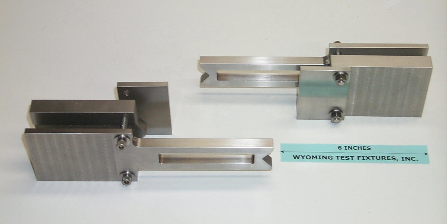
Fig. 1: Laminate bearing lateral support fixture, ASTM D 5961. Source: Don Adams
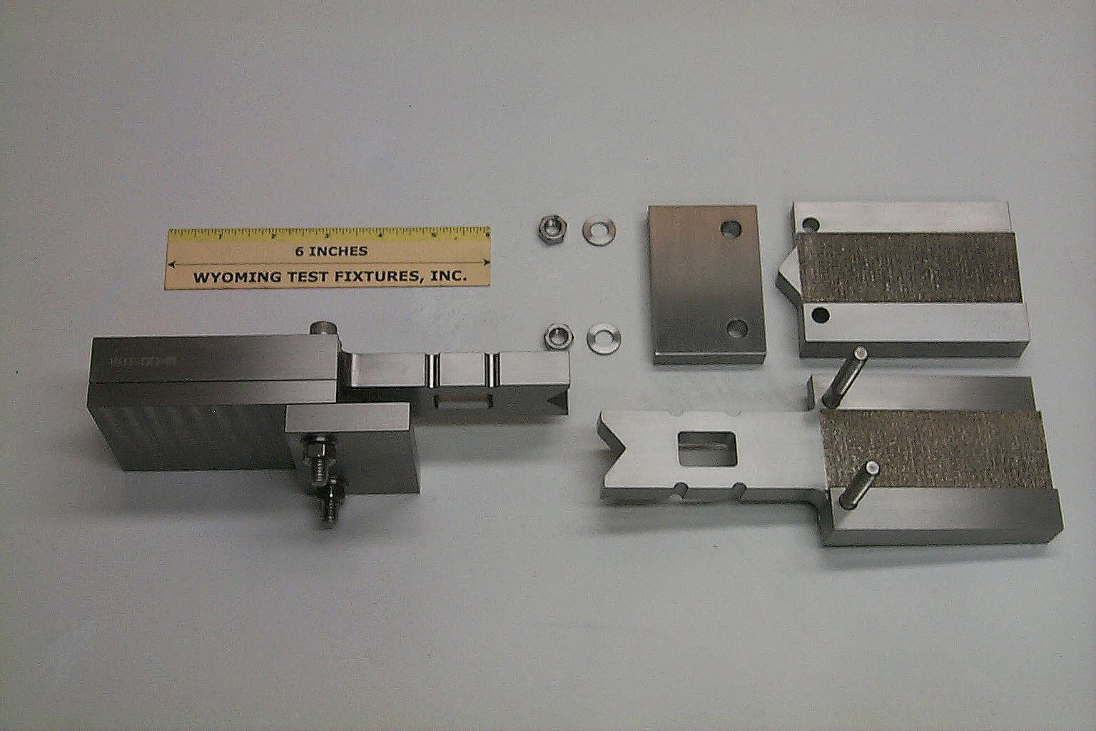
Fig. 2: Open-hole compression test fixture, ASTM D 6484 Source: Don Adams
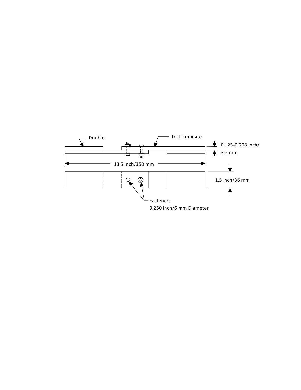
Fig. 3: Single-Shear, Double-Fastener Test Specimen, ASTM D 5961 Source: Don Adams
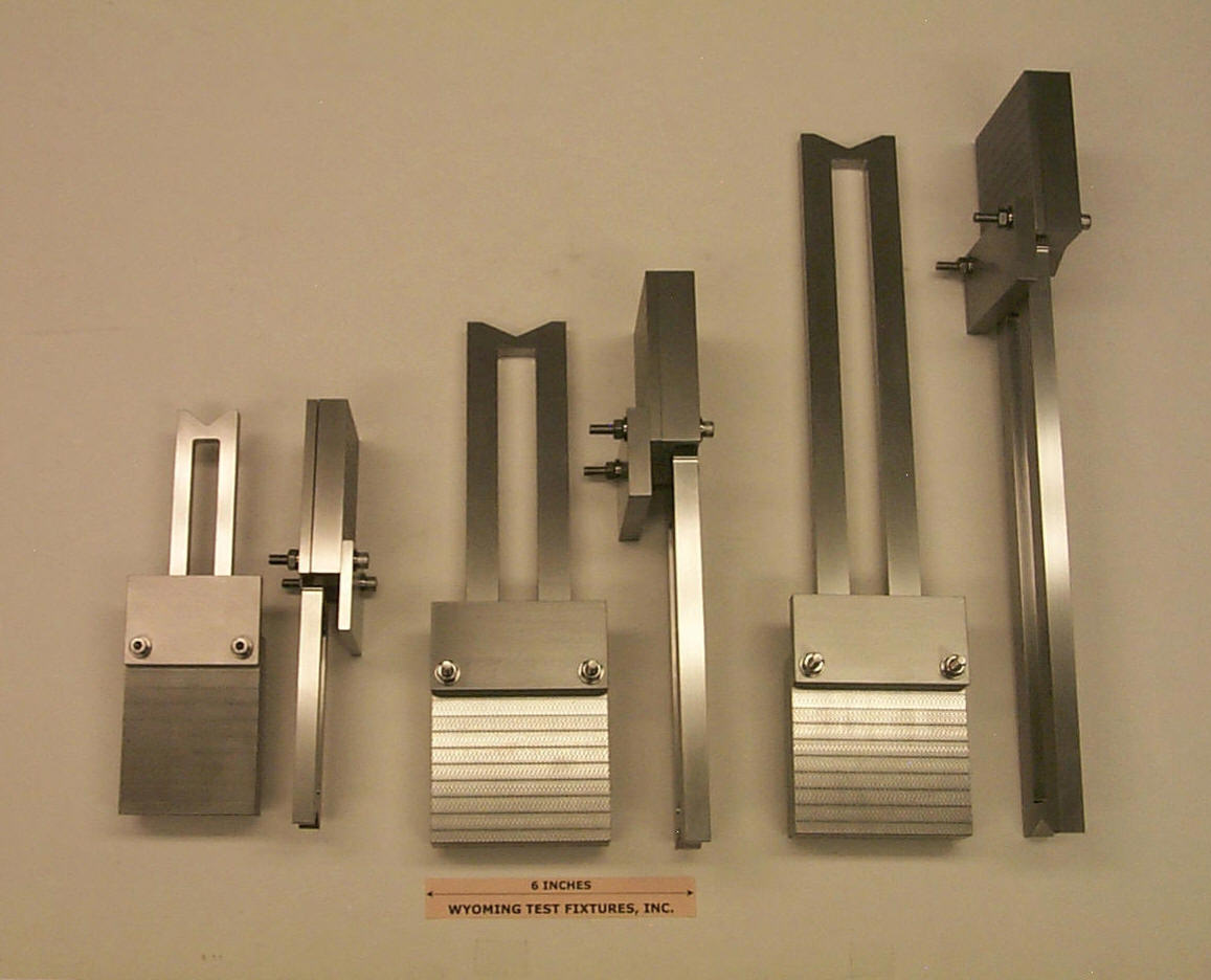
Fig. 4: ASTM D 5961 Fixture (left) and Two Oversize Fixtures Source: Don Adams
In my previous column, I discussed double-shear testing of a single fastener (see “Editor's Picks,” at right). But fasteners also can be subjected to single-shear loading — our subject this time — and, as noted previously, actual joints typically contain multiple fasteners that share the total load. Standards and associated test fixtures exist for controlling the portion of the load carried by each fastener.¹ However, it is of equal interest to load a multiple-fastener joint and evaluate the actual response directly, allowing the bypass loading to occur naturally. The governing standard for multifastener joints, ASTM D 5961-05² was first issued in 1996.
Unlike joints with fasteners in double shear, those containing fasteners in single shear are nonsymmetrical, which results in local bending of the fastened plates. Thus, even for assemblies loaded in tension, it might be desirable to provide lateral support in the joint region. Therefore, ASTM D 5961 was revised in 2001 to incorporate the laminate bearing lateral support fixture (see Fig. 1). The revised standard still considered only tensile testing of a single- or double-fastener joint and included the option to conduct tests with or without the lateral support fixture. When the fixture was not used, the intent was to simulate an unstabilized joint. When used, it was with the understanding that full stabilization would not be achieved, but rather a condition intermediate between unstabilized single-shear and symmetrical (and thus stable) double-shear loading would be realized.


We should note, parenthetically, two things. First, although the laminate bearing lateral support fixture (Fig. 1) is similar in general appearance to the fixture used for the open-hole compression test, ASTM D 6484³ (see Fig. 2 and “Related Content”), and each requires a specimen of the same width (1.50 inch/36 mm), the fixtures are not interchangeable. The obvious difference is the longer slot in the former to accommodate two fasteners, if used. But the more important difference is specimen length: The standard bolted joint specimen has a length of 13.5 inches/350 mm, compared to 12 inches/300 mm for the open-hole compression specimen. For that reason, separate fixtures are required for the two test methods. Second, the dimensions previously given are taken directly from the English and SI specimen drawings contained in the ASTM standards — they are not direct conversions. For the fastener test, the SI-unit specimen is slightly longer than the English unit specimen, while for the open-hole compression test, the opposite is true. These differences, of course, are the result of rounding off after unit conversions to simplify the numbers. Unfortunately, these approximations sometimes make it impossible to interchange specimens or fixtures, and, indeed, the standards caution against doing so. Until the perceived need for dual units goes away, it probably would be better for standards writers to use direct conversions rather than rounded numbers.
Although there was no reference to compressive loading of a joint in either the original 1996 or the 2001 revised version of ASTM D 5961, the latter’s introduction of the lateral support fixture prompted those already familiar with the open-hole compression test method and fixture to perform compression testing of joints. Consequently, ASTM revised D 5961 in 2005 to include compressive loading. Optional for tensile testing, the lateral support fixture is required for compression testing due to the obvious need to counteract not only induced bending but also gross buckling that can occur if adequate lateral support is not provided.
A sketch of a typical double-fastener test specimen is shown in Fig. 3. A single-fastener specimen has the same overall dimensions. The two pieces of test material are overlapped and fastened together. Doublers of the same thickness are added at the ends so that when the specimen is gripped the line of action of the applied force is along the centerline of the specimen. However, a bending moment still will occur in the central portion of the specimen. The support fixture attempts to restrain the out-of-plane deformation associated with this bending moment.
On the lateral support fixture plates (Fig. 1), the inside surfaces that contact the test specimen are thermal sprayed with tungsten carbide particles to enhance gripping. The two bolts at each end secure the side plates and hold the specimen in place as it is installed in the fixture. After specimen installation, the fixture ends are securely clamped in wedge grips. Hydraulic wedge grips usually are used to provide sufficient clamping force (independent of the axial loading) to prevent slipping. The grips must be wide enough (at least 3 inches/80 mm plus specimen thickness) and must open far enough (at least 0.90 inch/22 mm plus the specimen thickness) to accommodate the fixture. Although this opening requirement is less than that for grips used with the open-hole compression test fixture (at least 1.20 inches/30 mm), it will still necessitate use of hydraulic grips with 55,000 lb/250 kN or greater capacity. Not all labs have such large and expensive grips. For open-hole compression, ASTM D 6484 has been revised to allow direct end loading of the fixture as an alternative to shear loading (via wedge grips). This is not the case for the fastener test method, ASTM D 5961. In both methods, the specimen ends are (or can be) flush with the fixture ends of so that end loading should be successful in both cases, assuming sufficient stability can be maintained. But until this is verified experimentally, a change in the fastener test method standard is unlikely. This discussion, so far, has been focused on the standard lateral support fixture configuration. However, nonstandard fixture configurations are sometimes used to accommodate larger or smaller fasteners or more than two fasteners. Fig. 4 shows two examples of oversized fixtures that have been used, with the standard ASTM D 5961 fixture at the left. This suggests what can be done outside of the bounds of existing standards when the need arises. Nevertheless, most current testing is conducted in conformance with the standards.
References
1ASTM D 7248-07, “Standard Test Method for Bearing/Bypass Interaction Response of Polymer Matrix Composite Laminates Using 2-Fastener Specimens,” ASTM International (W. Conshohocken, Pa.), 2007 (first issued in 2007).
2ASTM D 5961-05, “Standard Test Method for Bearing Response of Polymer Matrix Composite Laminates,” ASTM International (W. Conshohocken, Pa.), 2005 (first issued in 1996).
3ASTM D 6484-04, “Standard Test Method for Open-Hole Compressive Strength of Polymer Matrix Composite Laminates,” ASTM International (W. Conshohocken, Pa.), 2004 (first issued in 1999).


Related Content

Testing to support composite bolted joint analysis
An overview of ASTM Standard Guide D8509, and its coupon-level mechanical testing of design properties for analyzing composite bolted joints.
Read More
Composite test methods (and specifications) for fiber-reinforced concrete structures
While initially focused on transitioning existing standards published by the American Concrete Institute, the relatively new ASTM Subcommittee D30.10 is developing new standardized test methods and material specifications for FRP composites.
Read More
Damage tolerance testing of sandwich composites: The sandwich flexure-after-impact (FAI) test
A second new ASTM-standardized test method assesses the damage tolerance of sandwich composites under flexural loading.
Read More
Measuring ply-wise deformation during consolidation using embedded sensors
Strip-type shape sensor method claims real-time measurement of ply-wise deformation.
Read MoreRead Next

Single-fastener, double-shear laminate bearing strength by tensile testing
Dr. Don Adams (Wyoming Test Fixtures Inc., Salt Lake City, Utah) discusses a laminate bearing strength test using double-shear loading of a single fastener.
Read More
“Structured air” TPS safeguards composite structures
Powered by an 85% air/15% pure polyimide aerogel, Blueshift’s novel material system protects structures during transient thermal events from -200°C to beyond 2400°C for rockets, battery boxes and more.
Read More
All-recycled, needle-punched nonwoven CFRP slashes carbon footprint of Formula 2 seat
Dallara and Tenowo collaborate to produce a race-ready Formula 2 seat using recycled carbon fiber, reducing CO2 emissions by 97.5% compared to virgin materials.
Read More