Formula 1 team accelerates design-to-track speed
Race car builder automates manual chassis design phase with unique FEA-to-CAD utility.
In Formula 1 auto racing, the job of designing and constructing a race car is a complex one, involving both problems and solutions unique to the craft. Today, carbon fiber composites are a significant factor in F1 design. Although they account for only 20 percent of the car by weight, they comprise about 80 percent of its structure by volume. But unlike OEMs in other fields where composites are highly valued for the design freedom they bring to product development, FI racing teams must hew closely to F1 racing rules and regulations, which effectively minimize the differences that can be designed into competing machines. Within those constraints, F1 design engineers constantly search for that one design or aerodynamic advantage that can shave fractions of a second from a lap time. Toward that end, each car in the team’s fleet is redesigned before each season, followed by incremental design changes during the season.
Simulation drives design
Here, F1 design is unusual in one other respect as well. Unlike the product development cycles in aerospace, marine and even consumer automotive markets, which begin with a CAD design and then migrate to analysis, the F1 cycle starts with optimization of simulation and analysis data in a finite element analysis (FEA) environment (fed by the previous year’s design), and then the simulation data drives the new design. FEA data are transferred to a CAD environment to create the car design, including carbon fiber ply schedules, core thicknesses and myriad other variables.
At ING Renault F1 (Enstone, U.K.), working backward from simulation data to CAD design involved a time-consuming process that robbed designers of optimization time. In the F1 world, what’s true on the track is true on the shop floor — speed wins. The faster a preliminary design gets off the drawing board and onto the test track, the more likely the team will capture the checkered flag. In a world where split seconds separate winners from also-rans, a creative but simple software solution gave the team a boost in speed that shaved days off its simulation-to-CAD lap time.
The Renault chassis
The ING Renault F1 team does all of its design and engineering work at its Enstone facility. Ian Goddard, senior CAE engineer for ING Renault, says the team uses 30 different types of carbon composite materials (woven and unidirectional) across six different types of resin each year to manufacture its race cars, spending £1.8 million ($3.58 million USD) annually on carbon fiber alone. ING Renault has a scant five months, starting in September, to design, manufacture and test a new car before the first race of the season in mid-March. During that time, says Goddard, new part drawings must be produced for about 7,000 of the roughly 10,000 parts used in the previous season’s design. Further, the actual simulation-to-design time frame is much shorter because certain production milestones must be met in the interim so that the car can be sanctioned by the Fèdèration Internationale de l’Automobile (FIA), the governing body of F1 racing.
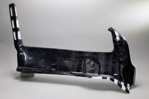
Of the 10,000 parts that make up each racing machine, none are more critical to its performance than those used to make the chassis. ING Renault makes about six chassis each race season. Each chassis, which measures approximately 60 inches long by 24 inches wide by 24 inches high (152 cm by 61 cm by 61 cm) is designed and manufactured in two halves, top and bottom, which are then bonded together to create the complete structure. Although it is not an aerodynamic element, the chassis supports the wings, body panels and spoilers that minimize drag, functions as the driver cockpit, provides the engine mount structure and is the structural center of the vehicle around which all the other components are oriented. Therefore, it must meet FIA strength and safety requirements, allowing the driver to walk away from or at least survive crashes that might otherwise be fatal. It also must bear the entire weight of the engine and all of the loads associated with it.
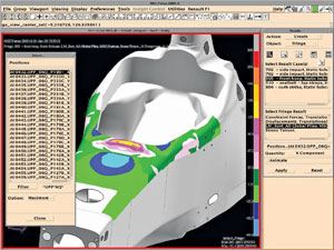
Because the chassis’ design is so performance-driven, Goddard, who manages the design and manufacture of the chassis, says ING Renault begins working what may seem backwards to each new season’s design by analyzing and optimizing the previous year’s design in MSC.Software’s (Santa Ana, Calif.) Patran FEA tool, assessing each of the 1,300-plus plies used to manufacture the chassis, integrating new aerodynamic surface and preliminary composite laminate information. To optimize strength-to-weight, the length, width and placement of each ply is carefully scrutinized.
“It looks a little like a patchwork quilt,” quips Goddard, “with stacks of carbon fiber plies here and there to provide strength exactly where we need it.” One of the reasons for the “patchwork” use of carbon fiber, explains Goddard, is to conserve weight above the vehicle’s center of gravity so that it can be added to the bottom of the car. The minimum weight of a Formula 1 race car, including driver and all nonfuel fluids, is 605 kg/1,334 lb, so the emphasis is on the keeping vehicle mass as close to the ground as possible to optimize handling.
The challenge, says Goddard, had been getting analysis data out of Patran and into the CATIA CAD environment (Dassault Systèmes, Paris, France) in which the designers work. Given the relative incompatibility between the applications, the analysis team had to manually generate data that roughly characterized the laminate configuration requirements of the new chassis. The design team then used printed views of each ply from Patran for manual interpretation and freehand modeling in CATIA, resulting in a design that roughly matched what the analysis team had done. But, Goddard says, the two never perfectly matched — ply schedules and ply boundary accuracy were particularly troublesome. Manual data transfer required up to two weeks, followed by another two weeks of design work to “tidy up” the CAD geometry to get it in a usable form.
Digital enlightenment
For several years, ING Renault has used VISTAGY Inc.’s (Waltham, Mass.) FiberSIM software as the foundation of its engineering process to help it design, simulate and manufacture composites parts for its race cars. In the spring of 2007, Goddard approached VISTAGY for help with its painstaking design process. “This was never brought to our attention before,” recalls Peter Ungaro, director of applications engineering at VISTAGY. “I think they just considered their existing manual design process as a given, as the only way that a new car can be designed.”
VISTAGY, because of its partnership with MSC.Software, began work on a data export tool that would enable Renault to digitally transfer its analysis information from Patran directly into CATIA. When VISTAGY delivered the software, Goddard’s understandably hesitant team first tested it on a few parts, but after the import utility transmitted the simulation data for 10 production parts to CATIA with 100 percent design accuracy, Renault was sold. The utility was fully implemented in fall 2007.
Used throughout the design and engineering of the chassis for the 2008 car, the software compressed the data transfer process from two weeks to about 60 minutes each for the upper and lower halves of the chassis. Because the data come straight from Patran, the design teams spend significantly less time fine-tuning and perfecting chassis design. The tool also enables ING Renault to automate or digitize ply orientation and ply books, thereby fully integrating the team’s design and simulation tools. A process that once consumed nearly four weeks now is complete in one week. “In other environments,” says Ungaro, “a savings of 17 days is a pittance. But here, it allows Renault to considerably increase the number of its aerodynamic and design iterations.” Goddard’s team puts the extra time to good use, redistributing weight. “It’s all about grams,” he says.
From spec to track
After the new chassis design is optimized, the chassis halves are molded in female carbon tools that have thermal properties similar to that of the material of manufacture. Tools are pulled from masters milled on a LinX CNC machine supplied by Jobs SpA (Piacenza, Italy and Fenton, Mich.). Plies are cut on a computerized cutting system provided by Lectra (Paris, France and Marietta, Ga.). Part layup is done by hand, guided by a laser ply placement system supplied by Assembly Guidance Systems Inc. (Chelmsford, Mass.). Of the 30 fiber forms used in the car, one-third are used in the chassis, and Goddard says that the chassis uses some but not all of the car’s six resin matrices, with epoxy being predominant. The sandwich construction features aluminum honeycomb core with thicknesses varying greatly depending on strength and structural requirements. Goddard says the structure’s thickness varies from just a few plies (sans core) in low-load sectors to 2 inches/51 mm in highly loaded areas, such as the FIA-governed air intake/roll hoop combination immediately above and behind the driver’s head and the back wall to which the engine is mounted. The chassis halves are autoclave cured in a process that Goddard calls “highly specialized, given the complexity of the materials.”
The new design is already being put to the test. The 2008 F1 racing season began March 16 with the Grand Prix of Australia. But Goddard is busy thinking ahead about the 2009 season. The FIA’s rule changes for the 2009 racing season already have been announced — including limits on the use of specialized aerodynamic “wings” and requirements to make cars more energy efficient and environmentally friendly — posing a new set of challenges for ING Renault designers.
Related Content
Highly tunable, woven lattice reinforcements target automotive structures
CAMX 2023: Startup Weav3D will be demonstrating its two collaborative automotive demonstrator parts and present two conference papers.
Read MorePlant tour: Albany Engineered Composites, Rochester, N.H., U.S.
Efficient, high-quality, well-controlled composites manufacturing at volume is the mantra for this 3D weaving specialist.
Read MoreComposite resins price change report
CW’s running summary of resin price change announcements from major material suppliers that serve the composites manufacturing industry.
Read MorePEEK vs. PEKK vs. PAEK and continuous compression molding
Suppliers of thermoplastics and carbon fiber chime in regarding PEEK vs. PEKK, and now PAEK, as well as in-situ consolidation — the supply chain for thermoplastic tape composites continues to evolve.
Read MoreRead Next
All-recycled, needle-punched nonwoven CFRP slashes carbon footprint of Formula 2 seat
Dallara and Tenowo collaborate to produce a race-ready Formula 2 seat using recycled carbon fiber, reducing CO2 emissions by 97.5% compared to virgin materials.
Read MoreDeveloping bonded composite repair for ships, offshore units
Bureau Veritas and industry partners issue guidelines and pave the way for certification via StrengthBond Offshore project.
Read More“Structured air” TPS safeguards composite structures
Powered by an 85% air/15% pure polyimide aerogel, Blueshift’s novel material system protects structures during transient thermal events from -200°C to beyond 2400°C for rockets, battery boxes and more.
Read More


