
Gripping composite test specimens: Options and guidance
Orthotropic behavior of composites test specimens makes load introduction uniquely challenging.

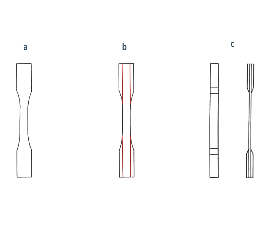
Fig. 1 Composite tensile specimen design
Fig. 1a: Dog bone-shaped tensile specimen
Fig. 1b: Longitudinal splitting of composite dog bone specimen
Fig. 1c: Tabbed composite tensile specimen
Source | Dan Adams
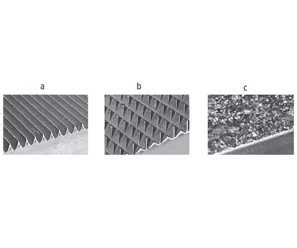
Fig. 2 Grip surfaces used for composites
Fig. 2a: Straight serrations
Fig. 2b: Crosshatched serrations
Fig. 2c: Particle-coated
Source | Dan Adams
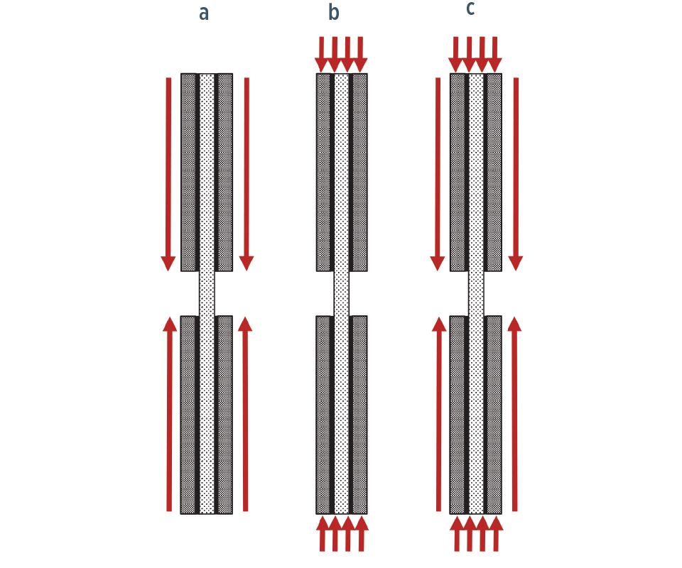
Fig. 3 Load introduction methods for compression testing
Fig. 3a: Shear loading
Fig. 3b: End loading
Fig. 3c: Combined loading
Source | Dan Adams
Share
Read Next


Regardless of the type of mechanical test being performed on composite materials, load introduction into the test specimen is among the biggest challenges. Fiber-reinforced composites have relatively high strengths when loaded in the fiber direction and, thus, relatively high forces must be transferred into the test specimen. However, unidirectional fiber-reinforced composites also have relatively low strengths when loaded in other orientations. This orthotropic material behavior — having different strength properties in different directions— makes load introduction even more problematic. Isotropic materials, such as metals and plastics, have the same strength in all directions. But the tensile strength of a carbon fiber composite, for example, is typically 20-30 times higher in the fiber direction than in the perpendicular direction. The shear strengths of unidirectional composites are relatively low as well.
The high fiber-direction strength and orthotropic material behavior of composites often preclude the use of specimen designs and methods of load introduction developed for use in testing metals and plastics. Consider, for example, the flat dog bone-shaped specimen that’s commonly used for tension testing (Fig. 1a, above). The specimen’s wider ends provide increased surface area for gripping and shear loading. The reduced cross-sectional area in the central region introduces higher tensile stresses that result in desirable test section failures. However, if this same concept is used with unidirectional composites, longitudinal splitting will occur, which effectively produces a straight-sided specimen (Fig. 1b). The reason? High shear stresses are produced in the width-tapering regions and unidirectional composites have low shear strengths.


For tensile testing unidirectional composites, end tabs typically are bonded to the top and bottom specimen surfaces in the gripping regions (Fig. 1c) to produce a greater cross-sectional area than in the central test section. The relatively large surface area of the bonded tab produces lower shear stresses, and the desired test section failures. Bonded tabs also provide a sacrificial outer layer that can be gripped without damaging the outer layers of the composite. Glass fabric/epoxy laminated circuit board material is most commonly used for tabbing. Guidelines for tabbed tensile specimen design and testing are provided in ASTM D30391.
Gripping of tabbed composite tensile specimens typically is performed using mechanical or hydraulic wedge grips. The 10-15° wedge angle on the grip inserts produces a clamping force that increases proportionally with the tensile force applied by the testing machine. Due to the variety of gripping requirements produced by composite specimens of different strengths and thicknesses, a variety of grip surfaces are commonly used. The greatest load introduction is achieved using straight serrations (Fig. 2a), which bite more deeply into the gripped surfaces. They’re also useful for accommodating surface irregularities. Crosshatched serrations, typically machined in a diamond pattern (Fig. 2b), are less aggressive but permit high load introduction when the gripped surfaces are not too irregular. For cases of reduced load introduction requirements and for relatively flat and smooth specimen surfaces, tungsten carbide particle-coated gripping surfaces (Fig 2c) in the range of 60- to 100-grit may be used. These surfaces minimize damage to the gripped surfaces and for that reason, in some cases, allow the use of untabbed specimens. Additionally, the use of unbonded friction tabs may be feasible for cases of reduced load introduction requirements. In this case, medium-grit emery cloth (with the grit-side toward the specimen) may be used with less aggressive wedge grip surfaces. When the gripping options are limited to more aggressive grip surfaces, such as straight serrations, butyrate plastic strips placed against the grip serrations followed by drywall sanding screen has been a successful strategy in cases of reduced load introduction. In any case, the abrasive layer must be able to withstand the compression and shear forces produced during gripping.
Compression testing requires similar adaptations and offers some additional challenges for load introduction into composite specimens. Like tensile specimens, compression specimens may be tabbed and shear-loaded through the tabbing surfaces (Fig. 3a). The most commonly used shear-loaded compression test method, ASTM D34102, uses straight serrations on the test fixture’s wedge grip surfaces for load introduction. Additionally, compression specimens may be end loaded (Fig. 3b). For many composites, bonded tabs are required to avoid crushing or splaying at the specimen ends prior to the desired compression failure in the central test section. The bonded tabs serve to increase the load-bearing area of the specimen ends, and the compressive forces introduced into the specimen tabs are transferred into the composite specimen via shear stresses along the lengths of the tabbed sections. The Modified ASTM D6953 test and the SACMA SRM 1R-944 test are commonly used end-loaded compression test methods.
A third method of load introduction for composite compression specimens combines shear loading and end loading (Fig. 3b). For this combined loading compression testing, it is desirable to introduce as much load as possible directly into the ends of the composite specimen without failure at the specimen ends. The remaining load introduction is obtained by shear-loading the specimen surfaces. The combined loading compression (CLC) test method, ASTM D66415, is one of the most commonly used compression test method for composites. The specimen-gripping surfaces of the test fixture are coated with tungsten carbide particles for shear loading. A combination of end loading and shear loading is sufficient for compression testing many woven fabric-reinforced materials and 0°/90° cross-ply composite laminates without the use of bonded tabs. However, bonded tabs are required for successful compression testing of most high-strength unidirectional composites.
One method of reducing the load introduction requirements for both tensile and compressive testing is by decreasing the specimen thickness. Unlike tensile testing, however, the thickness of compression specimens must be sufficient to prevent buckling from occurring during the test. In general, a thicker specimen and considerably shorter test section are needed when compression testing. Typically, the shortest practical test section length is selected, and the required minimum specimen thickness to prevent buckling is determined.
References
1ASTM D3039/D 3039M-17, “Standard Test Method for Tensile Properties of Polymer Matrix Composite Materials,” ASTM International (W. Conshohocken, PA, US), 2017 (first issued in 1971).
2ASTM D3410/D3410M-16, “Standard Test Method for Compressive Properties of Polymer Matrix Composite Materials with Unsupported Gage Section by Shear Loading,” ASTM International (W. Conshohocken, PA, US), 2016 (first issued in 1975).
3Modified ASTM D695 Compression Test Fixture, Wyoming Test Fixtures Inc. (Salt Lake City, UT, US), http://www.wyomingtestfixtures.com/Products/b2.html.
4SACMA Recommended Method SRM 1R-94, “Compressive Properties of Oriented Fiber-Resin Composites,” Suppliers of Advanced Composite Materials Assn. (Arlington, VA, US), 1994.
5ASTM D6641/D6641M-16, “Standard Test Method for Compressive Properties of Polymer Matrix Composite Materials Using a Combined Loading Compression (CLC) Test Fixture,” ASTM International (W. Conshohocken, PA, US), 2016 (first issued in 2001).


Related Content

Improving carbon fiber SMC simulation for aerospace parts
Simutence and Engenuity demonstrate a virtual process chain enabling evaluation of process-induced fiber orientations for improved structural simulation and failure load prediction of a composite wing rib.
Read More
Optimized approach to predict delamination failure in CFRTP structures
ARRK Engineering and Mitsui Chemicals improved delamination prediction accuracy to help optimize absorbed energy/failure load for an overmolded TAFNEX CF/PP UD tape bumper beam.
Read More
ATLAM combines composite tape laying, large-scale thermoplastic 3D printing in one printhead
CEAD, GKN Aerospace Deutschland and TU Munich enable additive manufacturing of large composite tools and parts with low CTE and high mechanical properties.
Read More
Nine factors to consider when designing composites cure tooling
Gary Bond discusses the common pitfalls and compromises when designing good cure tooling and their holistic significance for a robust composite production process.
Read MoreRead Next

VIDEO: High-volume processing for fiberglass components
Cannon Ergos, a company specializing in high-ton presses and equipment for composites fabrication and plastics processing, displayed automotive and industrial components at CAMX 2024.
Read More
All-recycled, needle-punched nonwoven CFRP slashes carbon footprint of Formula 2 seat
Dallara and Tenowo collaborate to produce a race-ready Formula 2 seat using recycled carbon fiber, reducing CO2 emissions by 97.5% compared to virgin materials.
Read More
Plant tour: Daher Shap’in TechCenter and composites production plant, Saint-Aignan-de-Grandlieu, France
Co-located R&D and production advance OOA thermosets, thermoplastics, welding, recycling and digital technologies for faster processing and certification of lighter, more sustainable composites.
Read More